-
Forum Statistics
7.9k
Total Topics52.5k
Total Posts -
Member Statistics
136,258
Total Members16,800
Most Online


PaYFrog Customs
-
Posts
21 -
Joined
-
Last visited
-
Days Won
3
Content Type
Profiles
Forums
Downloads
Events
Gallery
Blogs
Everything posted by PaYFrog Customs
-

[Buildlog] Thermaltake Core x9 - "White Memory"
PaYFrog Customs replied to PaYFrog Customs's topic in System Builds
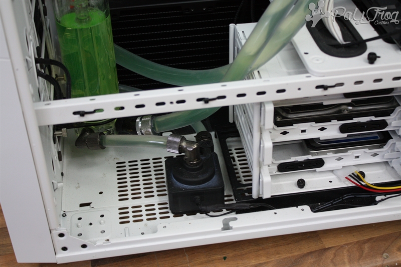
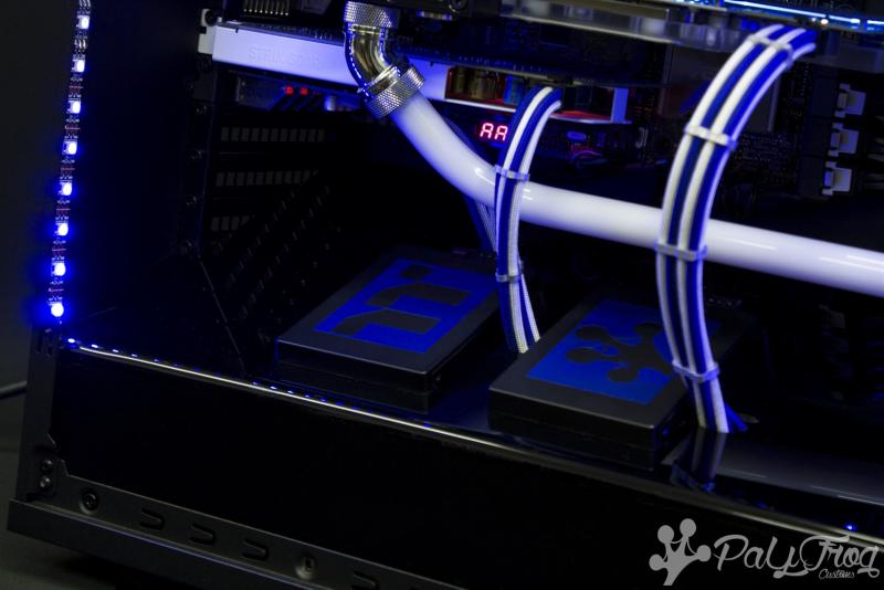
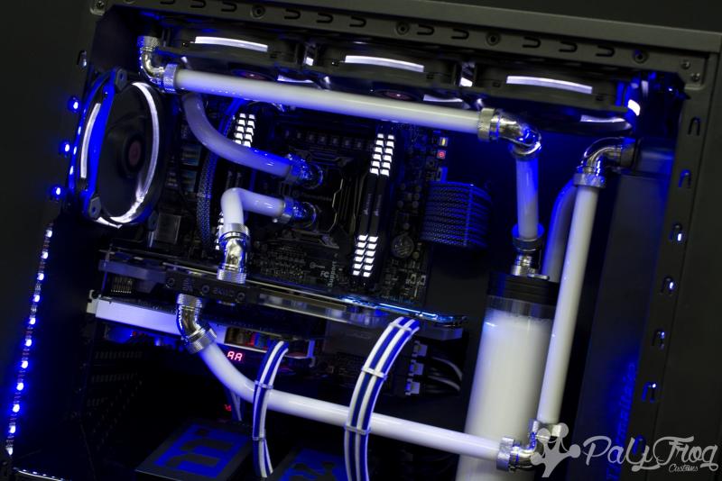
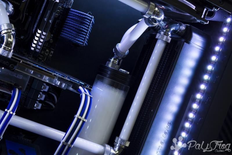
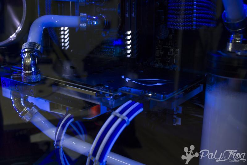
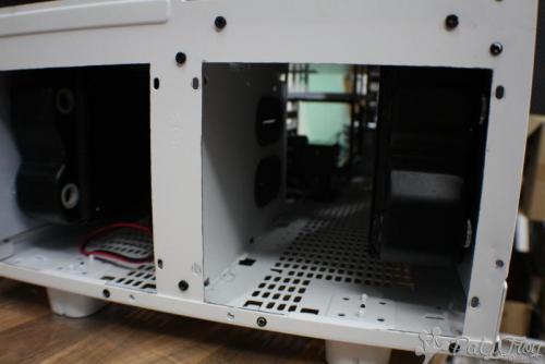
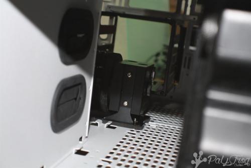
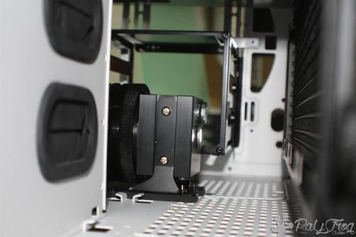
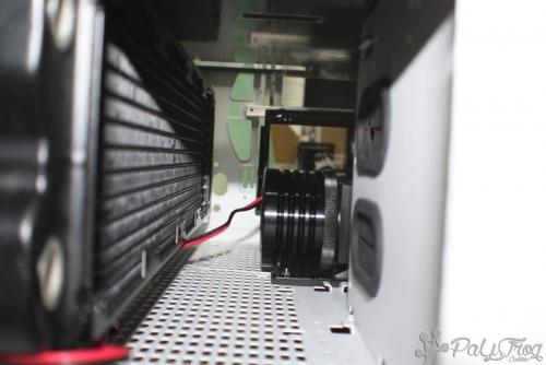
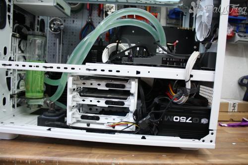
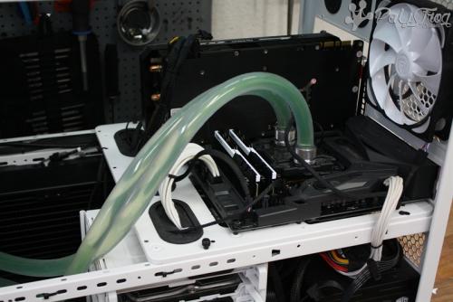
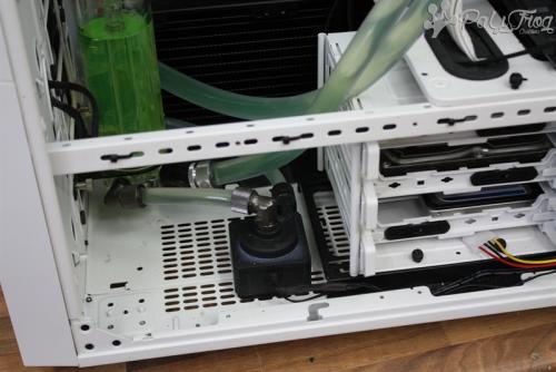
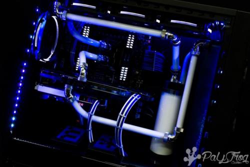
It's been some time since the last update on this project. This can be seen in the "Progress Photos" too. Apart from the dust, what happened? - - the radiators (2 x 480 mm / 60 mm) and fans have now found space in the lower chamber. - the wiring was largely completed (io is still missing). - the pass trough by the midplate has been tested; close! - the system has been filled. The final work will be completed in the next few days. Then everything will be removed from the dust again.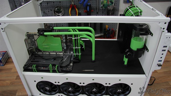
-
[Buildlog] Thermaltake Core x9 - "White Memory"
PaYFrog Customs replied to PaYFrog Customs's topic in System Builds
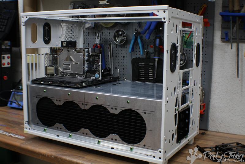
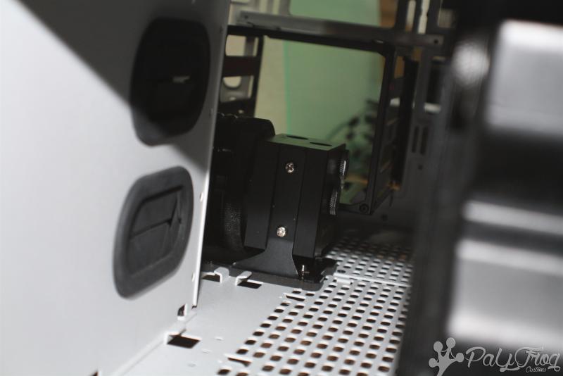
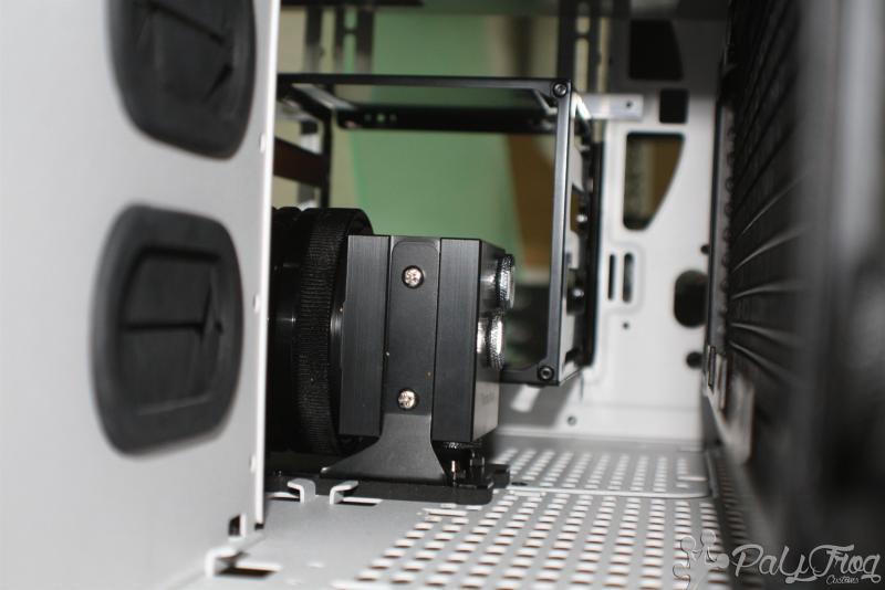
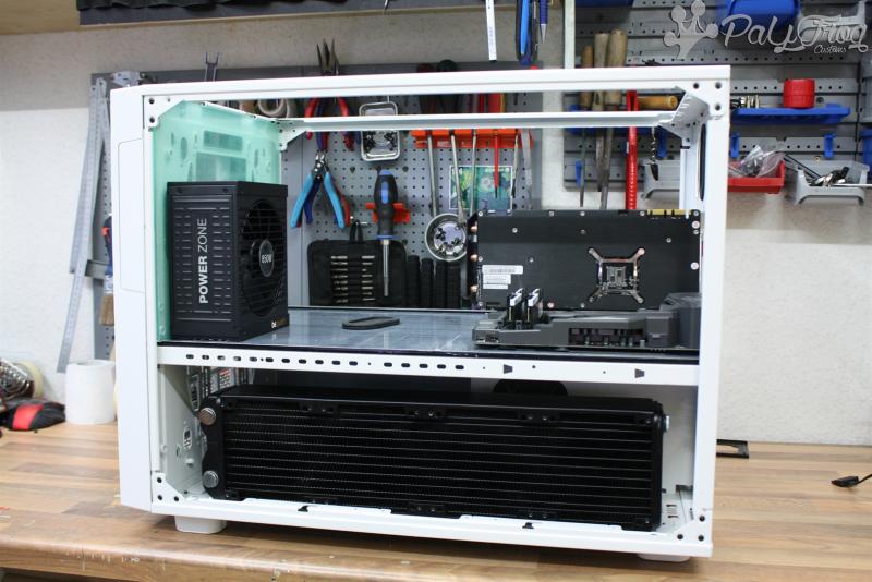
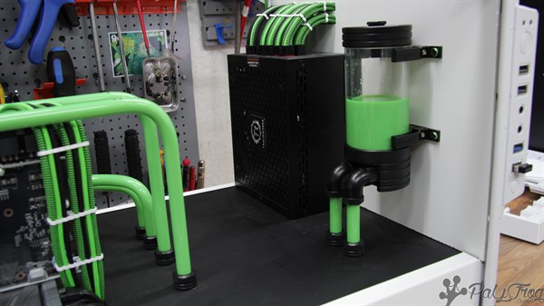
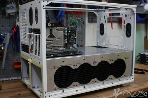
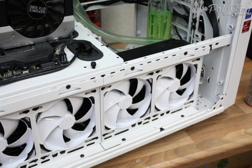
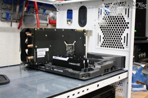
Today I have the first update for you. The sidepanels for the lower part of the case are finished. In fact of missing fans I mounted the radiators without them. The pump is allready mounted at the final position. The HDD cage is integrated in the front of the case. I hope you like it.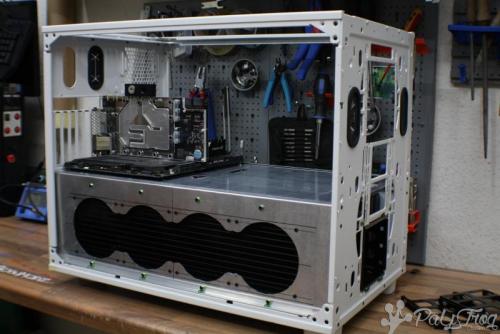
-
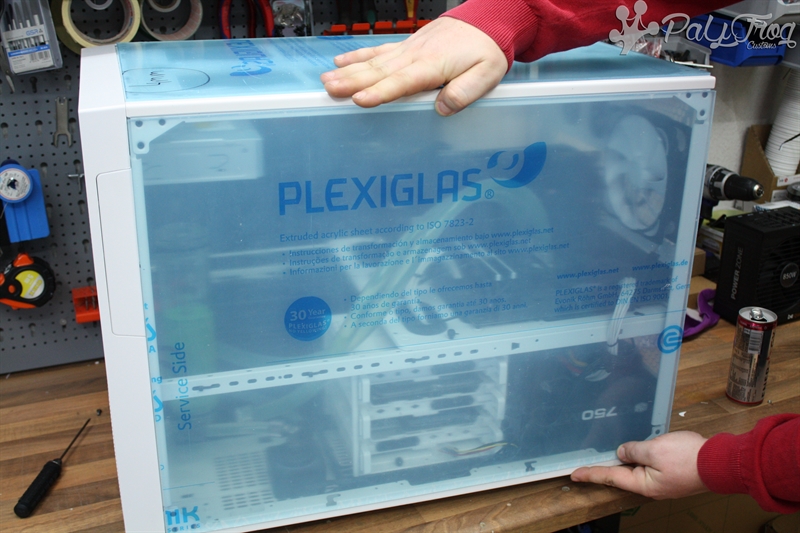
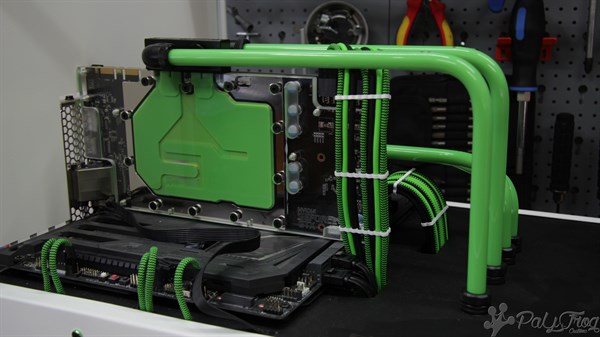
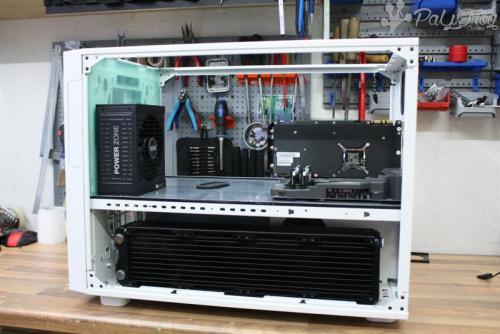
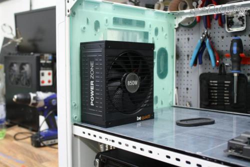
Dear PC enthusiasts, today I want to introduce to you my second Thermaltake Core x9 build. This time I want to do something other than last time. I allready made some changes, so you can still see the concept. Basement: Concept: The case will be seperated horizontaly. The lower part of the case will be holding two 480mm/60mm radiators. The new cover on each side of the case will hold one of them. Behind the front I will add an HDD/SSD cage, so you can mount them easily. The PSU will get a new position in the upper of the case. Mounted right behind the front, you got a great view on the PSU and the cables. Next to it I will mount the reservoir and go straight to the midplate into the lower section of the case. To get a good view all over the case I will install acrylic plates in the top and both sides. Hope you like this build. Stay tuned

-
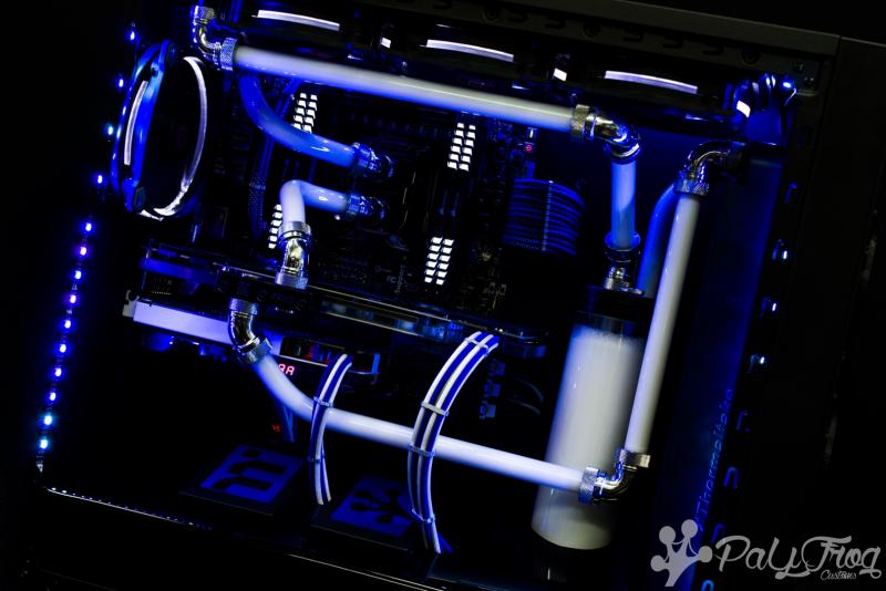
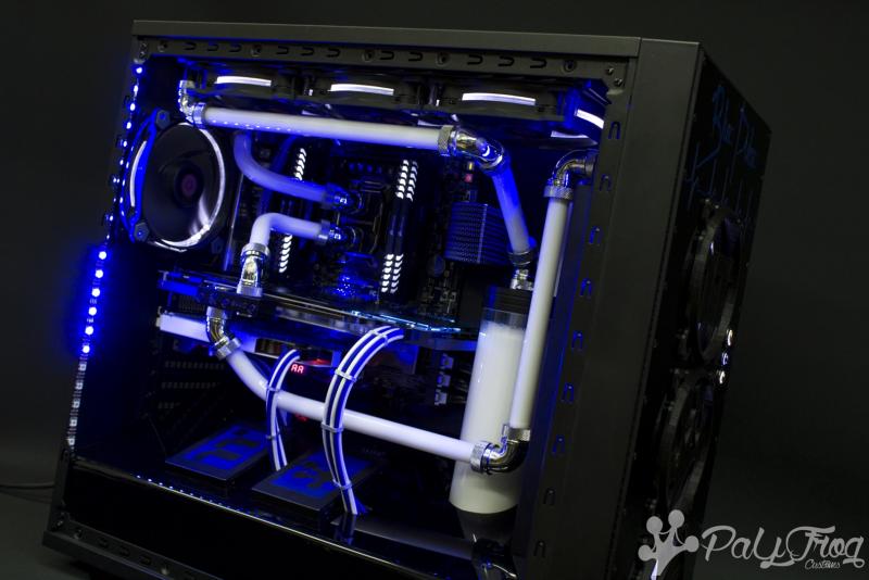
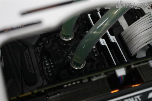
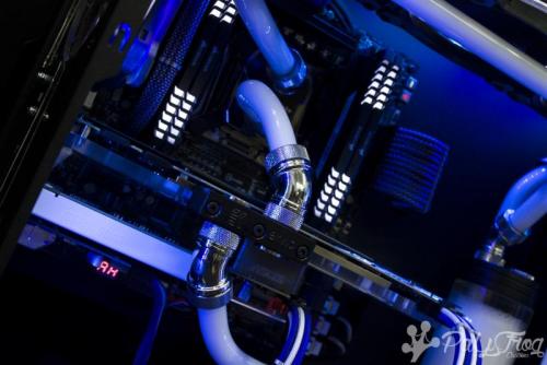
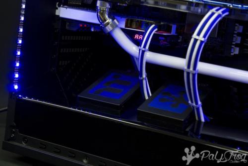
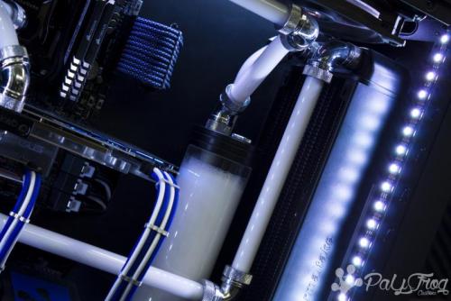
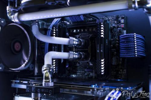
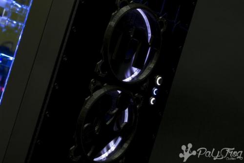
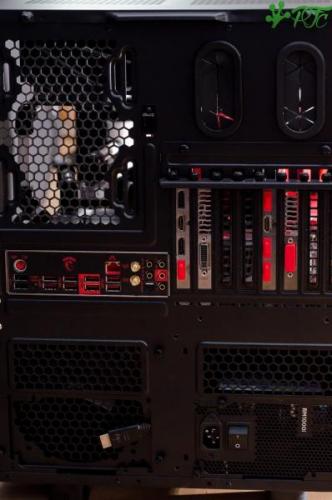
today there are pictures of the "Blue pulse" for you. A special thanks for the support of this build goes to Thermaltake Germany. The project was launched in December in a live stream hold fr - so. After the stream there was a still a few little additions. Including a specially for the mod programmed lighting. This has several effect Modi and color from blue to white. The lightning will be shown in a upcoming videoclip. Changes: Motherboard Tray / rear / front cleaned. Power Supply Cover. (SSD Mount and reservoir hole) Sleeved custom cable, (MB and pci-e cards separated) Addressable Leds with different effects. Specs: Intel I7 6800k Asus x99m WS/SE Asus GTX 1070 Strix OC Asus Strix Soar Corsair Vengeance LED 4x8Gb 2666MHz Thermaltake Smart DPS G680W Kingston HyperX 480Gb SSD OCZ 120Gb SSD x2 1Tb + 1Tb + 1,75Tb HDDs Cooling and Case: Thermaltake Core x31 Thermaltake Riing 12 white x7 Thermaltake Pacific PT40-D5 Thermaltake Pacific R360 Radiator 25mm Thermaltake Pacific RL360 Radiator 60mm Thermaltake Pacific W1 CPU Water Block Thermaltake C1000 Opaque Coolant White Thermaltake V-Tubler PETG Tube 500mm (4 pack) x2 Thermaltake Pacific G14 PETG Tube 45-Degree Compression 16mm OD – Chrome Thermaltake Pacific G14 PETG Tube 90-Degree Compression 16mm OD – Chrome Thermaltake Pacific PETG Tube 90-Degree Dual Compression 16mm OD - Chrome EKWB EK-FC1080 GTX Strix - Nickel Video Links: Part 1: https://youtu.be/xlsNN1aSVkE Part 2: https://youtu.be/PBeThBlz1jw Part 3: https://youtu.be/5u4OKjJf4F8 Part 4: https://youtu.be/4ZYesJOcRIU


-
BuildLog - Thermaltake x9 (nameless; open for names..)
PaYFrog Customs replied to PaYFrog Customs's topic in Modding
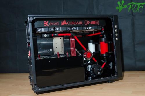
Today I will show you the final pictures of the Thermaltake Core x9. My friend who ownes the build was kind enough to send me some photos. At the time I finished the build there was so many stress that I can´t made them myself. The sidepanels were removed for the photos in order to cancel the mirror effect. The sidepanels where rebuild with acrylic plates.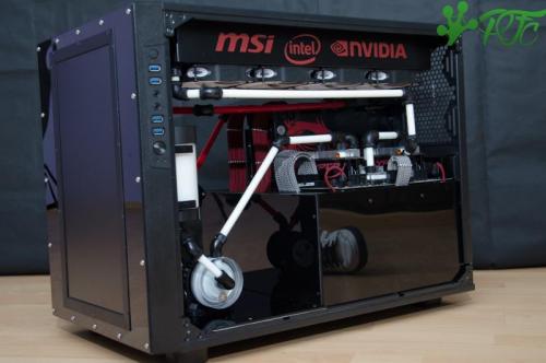
-
BuildLog - Thermaltake x9 (nameless; open for names..)
PaYFrog Customs replied to PaYFrog Customs's topic in Modding
My dear friends, we are approaching the end. Yesterday the Liquid has arrived and today I have prepared the system to fill. If the frame of the screen is painted, the front is completed. On the side walls I am already working. Tomorrow they will be painted. I hope you enjoy it. -
BuildLog - Thermaltake x9 (nameless; open for names..)
PaYFrog Customs replied to PaYFrog Customs's topic in Modding
At moment I can´t find the time to OC my graphic card. Be sure I don´t forget you. -
BuildLog - Thermaltake x9 (nameless; open for names..)
PaYFrog Customs replied to PaYFrog Customs's topic in Modding
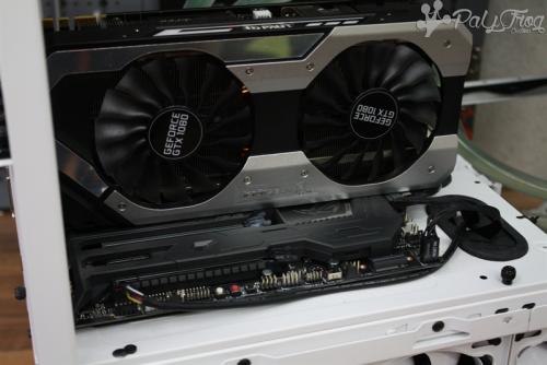
It´s an Inno3D ref yes. But I set the powerlimit to 300W so i think it´s ok to burn under air cooler. I can test my 980gtx tomorrow. -
BuildLog - Thermaltake x9 (nameless; open for names..)
PaYFrog Customs replied to PaYFrog Customs's topic in Modding
Hey, this build is for a good friend of mine. The motherboard, GPU, CPU, etc. are existing parts from his old PC. At moment I can´t say something about this. I will OC the hardware after finishing the PC. It isn´t only for aesthetics, I have a "old" 780Gtx, with a Aquacomputer water cooler. If I would try to run it with air the mosfets will be burned after less then 5 minutes.. -
BuildLog - Thermaltake x9 (nameless; open for names..)
PaYFrog Customs replied to PaYFrog Customs's topic in Modding
Today I once again taken the time to do something more. Currently there are to do a lot of other things, but the system needs to be done. A huge thanks go to Nanoxia! All angles, whether the G1 / 4 or 12/10 submitted by CoolForce, they have been put to me by Nanoxia. The quality of the fittings and angle is very good. The 12/10 fittings fit very great on the Tubes. Cables for GPUs and motherboard have been laid and adapted to the power supply inside. I hope you like my work. -
Guide: How to connect 9 Riing RGB fans to 1 controller box
PaYFrog Customs replied to PaYFrog Customs's topic in Case Fan
Here I have a small video to show the usage of some buttons for the controller. I´m sorry for the quality, it will be better in the future. https://youtu.be/GGbyAEh-49w best regards PaYFrog -
Guide: How to connect 9 Riing RGB fans to 1 controller box
PaYFrog Customs replied to PaYFrog Customs's topic in Case Fan
Hello, what exactly is going on with it? How many fans do you run with it an how do you connect it (Motherboard or PSU)? Thanks man, I have a lot of work at my house at moment but will try to Upload it fast. -
BuildLog - Thermaltake x9 (nameless; open for names..)
PaYFrog Customs replied to PaYFrog Customs's topic in Modding
I have a small update today. I have finished the cables for the graphic cards an the motherboard. The front of the case got a acryl plate wich fits very well. -
Guide: How to connect 9 Riing RGB fans to 1 controller box
PaYFrog Customs replied to PaYFrog Customs's topic in Case Fan
Not everybody is looking in Facebook for information. -
BuildLog - Thermaltake x9 (nameless; open for names..)
PaYFrog Customs replied to PaYFrog Customs's topic in Modding
Most of the acryl plates in the inner of the case are cutted and fixed. The screws will be changed and combined with washers from Grosumodz. The cables of the pumps are now sleeved and out through the bottom. Between the floors, I cleaned up a bit. The edges of the acrylic plates still get a chamfer, then they can already be painted. The case will be painted again, when everything else is finished. Most of the acryl plates in the inner of the case are cutted and fixed. The screws will be changed and combined with washers from Grosumodz. The cables of the pumps are now sleeved and out through the bottom. Between the floors, I cleaned up a bit. The edges of the acrylic plates still get a chamfer, then they can already be painted. The case will be painted again, when everything else is finished. This is it for now. Starting today I will post all updates. I hope you enjoy my project. -
BuildLog - Thermaltake x9 (nameless; open for names..)
PaYFrog Customs replied to PaYFrog Customs's topic in Modding
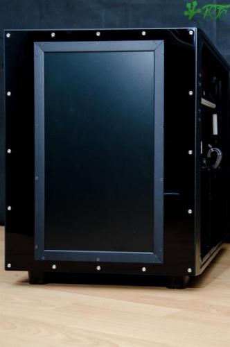
The inner of the case got some new stuff. I´ve mounted the resorvoirs und fixed the acryl. The radiators got some decals and the plan for the front is set now. The first thing I made was a frame for the display that will be insert in the case. I found some aluminium profiles that I didn´t used at another project. They fitted perfectly with the display. I had to make some changes at the profiles, so that they fit in the front. Between the profile and the case I will insert a 3mm black acryl plate. At the front of the case I made a cut for the cables. In order ti hide them I lead the cables unter the acryl plate of the pumps. The power supply and the HDMI cable for the display are already laid. After this was done, I have begun milling the first cable openings into the acrylic plate under the motherboard. I am not finished yet and still needs a little reworking. Everything is just done by hand and I am not a CNC milling machine. -
BuildLog - Thermaltake x9 (nameless; open for names..)
PaYFrog Customs replied to PaYFrog Customs's topic in Modding
I decided to cut some parts of the case cause it doesn´t fit for me. For the graphiccards backplate i made some decals as my friend wished. Then i did some work to clean up the inner of the case. A great thanks for a nice support to Nanoxia, the CoolForce angle fits quiet nice. To fit the motherboard I made some holes in the acryl plate of the mainboardtray. The pumps are already mounted. -
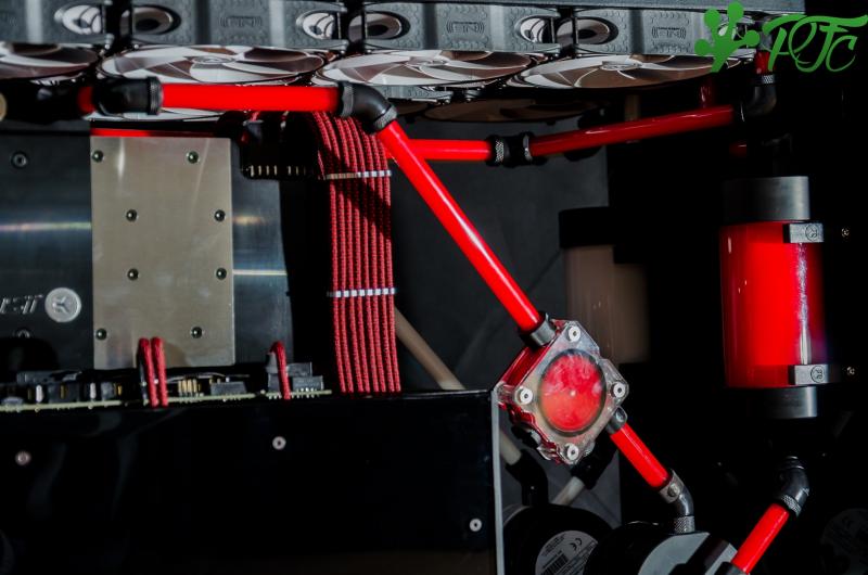
Hello, I want to share with you what i do in my freetime. I´m building pc´s for some of my good friends and this is one of them. It is still in progress and i´ve done some work actually. I know it´s much for the first post, but I missed to post this project here... Specs: Tower - Thermaltake x9 Cooling - Custom Watercooling with 2 loops Hardware: CPU - 5930K GPU - MSI GTX980Ti Gaming 6G (2x) MB - MSI Gaming 9 ACK RAM - HyperX Predator 2800mhz (4x8gb) PSU - Corsair RM1000i (Custom cable) SSD - ?? HDD - ?? Cooling: CPU - EK-Supremacy Evo Nickel GPU - EK-FC980 GTX Ti Acetal+Nickel MB - EK-MOSFET MSI x99 Gaming Nickel RAM - EK-RAM Monarch x4 Nickel / EK Ram Monarch Module Black Pump - EK-XTOP Revo D5 PWM - (incl. Pump) / EK-XTOP Revo D5 PWM - (Plexi incl. Pump) AGB - EK-RES X3 150Lite Radiator - EK-CoolStream XE 480 work in progress. I did the first test for the positions of the components. The inner of the Case will be coverd with Acryl. The front will get a special feature. Then I made a few components ready for watercooling. One graphics card cooler was still missing.
-
Guide: How to connect 9 Riing RGB fans to 1 controller box
PaYFrog Customs replied to PaYFrog Customs's topic in Case Fan
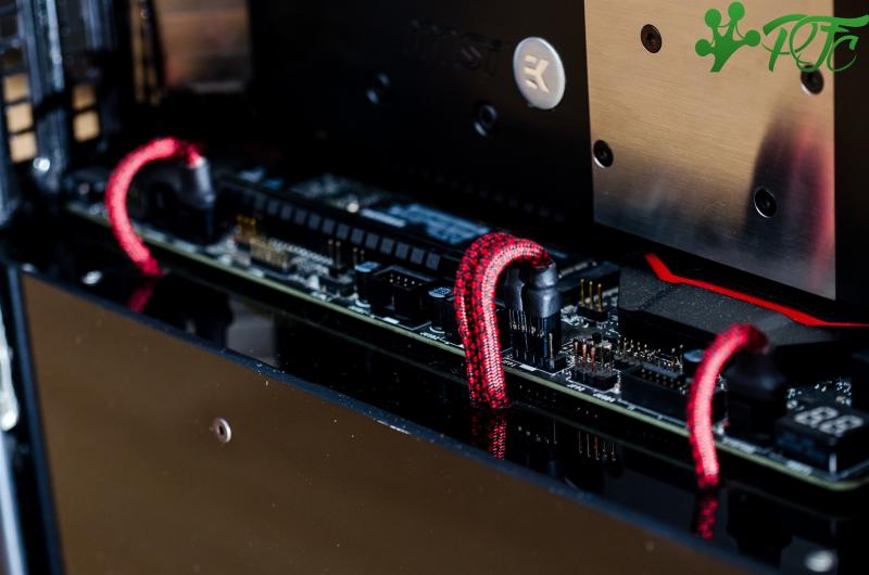
I added a picture to the post. Now you can see how i add the cable on the board. Video is coming up soon. -
Guide: How to connect 9 Riing RGB fans to 1 controller box
PaYFrog Customs replied to PaYFrog Customs's topic in Case Fan
Hey, I got my out of another controller. The only shop I know is aliexpress, there you can get those. http://de.aliexpress.com/item/100pcs-Lot-5-Pin-Connector-Leads-Header-2-54mm-KF2510-5P-Kit-Housing-Pin-header-Terminal/828195538.html?spm=2114.010208.3.198.a2ZD5G&ws_ab_test=searchweb201556_0,searchweb201602_2_10017_507,searchweb201603_2&btsid=4c7b53fa-3394-4e8c-ae7f-8b16efd76b86 The cables for the buttons has been soldered in the pcb. I will upload a picture of it tomorrow. Best regards. -
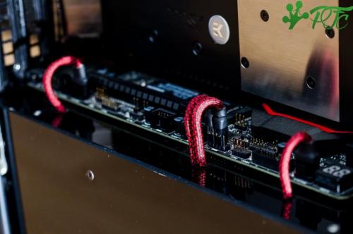
ForewordHello, my name is Dirk from PaYFrog Customs and today I want to show you what I figured out while playing with the controller of the Thermaltake Riing RGB fans for my Thermaltake Core P5 mod. The controller you receive whit the fans has a lot more potential than you would think. Open the controllerBefore we are going to use the controller for something it is not intended for, we should know what is inside of it. So I first opened it to know how it is looking inside. To open the controller, we have to unscrew four PH2 screws in the corners of the controller. The interiorThe interior has a very simple design. On one side of the circuit board we can see five pin headers, three for the fans (5pin, red), one for the power supply and PWM signal (4pin, green) and one for the optional connection cable (blue). Also, we see two mosfet (purple) for the circuits of the controller. On the other side of the circuit board we can see three switches and one status LED. We can set the controller’s functions with these switches but this isn’t the only way to do this. Functions of the boardLet’s take a look at the two mosfet. One of them is for the 5 Volt supply of the LED controlling unit and the LEDs. The other one for the supply of the fans. Both circuits can be set with the switches on the other side. One of the switches will set the fans to performance or silent mode, you can see which mode is activated if you´re looking for the status led. The other two switches will be used for the lighting of the fans. You can set the programmed colors or the “rainbow†mode with the first one. If you’re using the rainbow-mode, you can pause it with the second switch, so you can show any color permanently. There is still one problem, if you restart your pc you have to set them again. Fan connectorsPinoutWe have three pin headers for the fans. They looking quite similar to other fan connectors, but they are very different. The first thing we can see is that they got five pins. The only two pins that are similar to other connectors are the first and second pin („GND – Pin 1“ and „12V – Pin 2“). The last three pins are used for the LED controlling. The only thing I found out for now is the pin for the 5V supply, I can´t figure out which one is the data pin or what signal they are using to control the LEDs („Pin 3 – Y“, „Pin 4 – P“, „Pin 5 – 4,5 - 5V“). Max. tested fans/channelI for myself was running 3 fans per channel, that makes me running 9 fans on 1 controller. I had no problems with it. Of course you shouldn´t supply that with your motherboards fan header, so we will change the power supply for the controller. Unfortunately, this also gets rid of the PWM signal from the motherboard but we’ll get that back later with a little trick. Construct the splitterIt is really simple to build a splitter. We are going to split all pins to get more connectors. Likewise, a normal y-Splitter. First step: You need 3 headers for the fans. Step two: Be sure that they can’t touch each other to avoid damages and short-circuits. Step three: Bring them together at one connector. External buttons to set the controllerYou can use external buttons to control the light and speed of the fans. In my case I disassembled the pin header because I do not have the right material to plug something in. To show you how it works I will connect three buttons and make a video. The video will be uploaded in 2-3 days. Power supply for the controllerConfigurationWe want to use more than 3 fans at the controller, that means we have more than 3 fans at the fan header on the motherboard. I don’t want to damage anything and connecting more than 3 fans to one fan header on the motherboard should be avoided to prevent damage. I spliced the cable of the power supply in order to prevent damages. In that case the motherboard is used to regulate the fan speed only. Construct the cableThis is the simplest job of all. You have to trim the sleeve a little bit and change the connector for the 12V and GND. I for myself have added a normal Molex 4 pin connector for an easy plug and run. I´ve done this because I want to control the speed of the fans, but I didn´t want the motherboard to power all of them. I have extracted the 12V and GND only from the original connector so that we still can use the rev counter and the pwm signal of the controller to connect them to the motherboard. This is a usual setup at pwm pumps for a water cooled setup. Now we´re ready to go, the speed control can be set in the bios of the motherboard and the power supply is managed directly from the psu. Closing wordsI hope you can understand all this. I did this because I did not want 3 controllers on my Mora3. I don’t regret it, but you know it´s your own decision if you want to do the same. If you have any questions feel free to comment and I will do my best to help you.