-
Forum Statistics
7.6k
Total Topics50.9k
Total Posts -
Member Statistics
135,991
Total Members16,800
Most Online

Colin McNally
-
Posts
17 -
Joined
-
Last visited
-
Days Won
10
Reputation Activity
-

 Colin McNally got a reaction from Lorraine C. Davis in Colin McNally - project motogp
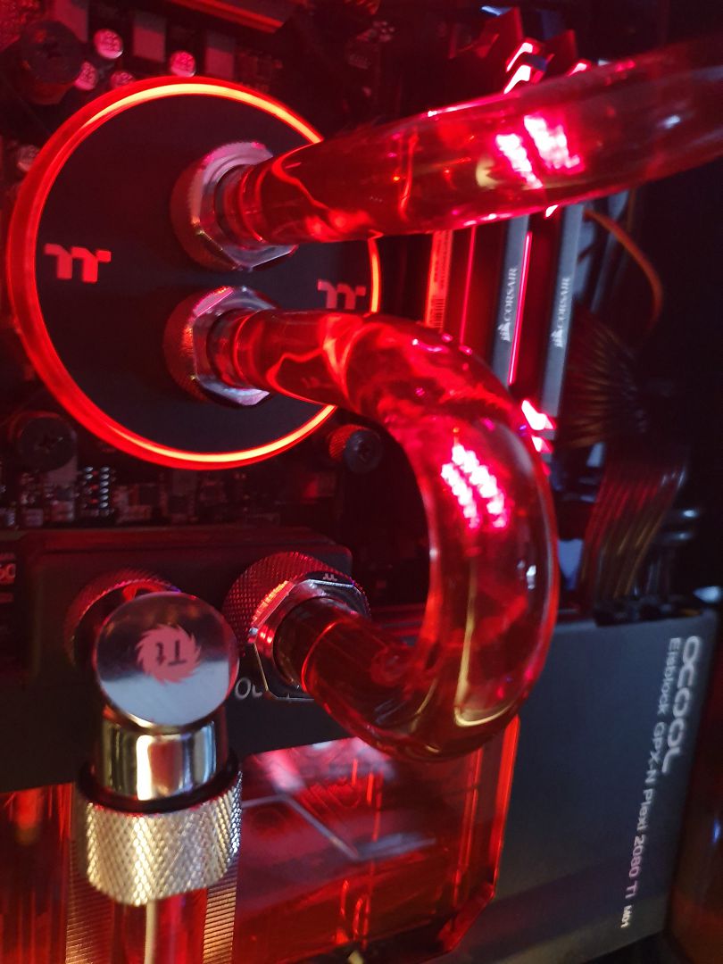
Hi all back with my weekly update and over the last week iv started to fit the waterloop.
I started with the gpu waterblock which I always get nervous doing.
When I figured out what way the pipes would run I started bending.when I got all the pipes in i filled with distilled water to test for leakes and clean the system out.
Now I've got to adjust the pipe and change the coolant to white. Its getting close now not much left to do so hopefully next week my build will be done.😁
-
Colin McNally got a reaction from Lorraine C. Davis in Colin McNally - project motogp
Finally here with my final build post. It's been fun and stressful but its done. Thanks to all the sponsors
Thermaltake
Scan computers
Amd
Seagate
Asus
I've put white coolant in added some stickers and some finishing touches
I'm happy the way it come out in the end.
Good luck to the other competitors in the tt2020casemodchallenge
-
 Colin McNally got a reaction from AcuteJungle66 in Colin McNally - project motogp
Finally here with my final build post. It's been fun and stressful but its done. Thanks to all the sponsors
Thermaltake
Scan computers
Amd
Seagate
Asus
I've put white coolant in added some stickers and some finishing touches
I'm happy the way it come out in the end.
Good luck to the other competitors in the tt2020casemodchallenge
-
 Colin McNally reacted to Andrew Makin in Project: I.S.A.C. by Andy Makin
Ahoy hoy Mod fans!
A working week since the last update, quite a lot of that time has been spent on a rather large piece of work that I can't show just yet. 32 pieces measured and cut, 102 holes drilled, come to construct it and one of the 2 types of bolt I'm using was too short 😖 Just 2mm longer and would have been fine. 🙄 But new bolts should be arriving in the next day or 2.
That's what I've been working on in the shed during the day, but in the evening I've been working on case internals, especially the wiring. Seems even my tools are Division themed 😂
First off are the 36 motherboard cables for the front section, which are all going to be pretty darn short.
Then the GPU cables, which have a path even Lewis Hamilton would struggle with. You can also see the loop starting to take shape and 2 nifty little brass ball valves that will be being used.
I was very lucky as the 18AWG wire I got from Pexon is too thick to fit into the GX16 connectors, but luckily I had that orange wire got just before the comp when I was planning something with my own rig. Had just enough to get all the front section wires, apart from 1 of the GPU wires, came up just 1 inch short. 😟 So the 6 pin connectors will get 2 orange and 1 white and will hopefully be able to hide the thicker wire in between all the others.
There's also been lots of other little fabrication and case work been done. Knocked out these brackets, which you may tell from the treacherous proximity of the countersunk holes to the edge and hastily shortened bolts wasn't quite fully thought through. 🤔
But they work 😄
And now you can see the reason for the deep scoring on that 2nd PSU mount cover. There will eventually be something a little more secure than just a thumbscrew to hold the cover in place 😜
The pump/res is going to be mounted on top of a shoggy sandwich to kill vibrations and noise, but I can't just plank a fat wedge of foam under it and call it a day, so I made a housing for it and got it glued and clamped, but it's still in the shed curing. I might put some holes in the side as the orange and black of the foam fit the colour scheme and a few round holes will make the alu angle look a bit more structural.
As the THICC 360 rad will be going in the front chamber and fan in the rear, I needed to make a 30mm hole for it's drain-port and Thermaltake's brilliant rotating drain valve.
As well as that there have been a few minor modifications made to the case here and there. I cut out the last rung of the vertical rad support as it wasn't going to be used and was in the way of the pass-through section. A couple of cable tie points needed to be Dremeled off as they got in the way of things, few other holes for cable routing and such and I modded the GPU support bracket to cope with it's decreased living space, but forgot to take any pics. There will be plenty later don't worry 😉
Also needed to put in a few more holes to the new motherboard tray, mostly along the bottom edge. 4 small holes for it to be screwed into the original tray and keep the lower edge steady, 4 larger holes for cable pass-throughs. There's also a couple of holes will sit behind the motherboard itself for a little sneaky sneaky cable management 🤫
That's all for this update folks. A lot of the work being done now with the cables and everything is just very fiddly and awkward and visually very unimpressive. Hopefully have something very soon for you that is. As it's now so far into crunch time that I've no teeth left, I might just pop in with the odd pic here and there. T-minus 7 days 7hours 7 minutes....... Until then Crap fans, stay tuned! Same Crap time, same Crap channel.
-
Colin McNally reacted to AcuteJungle66 in Chris Connor - Project SparklePony - #TTUK2020CaseModChallenge
Has it already been a week since the last update?
Well, I better get cracking then!
So the next thing I wanted to get sorted out was the panelling/trim on the 'business side' of the case. I kind of had an idea of how I wanted it in my head, but thought it safe to try with foamboard first.
Which is just as well, since the prototype was a fair bit wonky:
But at least it served its purpose, it enable me to fine tune things a fair bit before moving on to the actual acrylic pieces.
So a little bit of jigsaw action resulted in:
So my inital thoughts were that I was at least happy with the shape and relative symmetry of it, and I like that some of the lighting was coming through the acrylic; but ultimately I decided that I would like it better if I painted it.
Which then gave me an idea. What if I put on some stars (as in the stickers we used to get at school for doing a good job), painted over it and then peeled them off? I wonder if that would work:
So slapped some primer on it and put it to one side for now, as I wanted to turn my attention to the front and top panels:
Managed to get it bonded at least, but I knew that getting the seams all smoothed out would require a little bit of elbow grease later on.
Same with the front, quite a bit messy here as I was slapping it on there a fair bit. But it was nice to see how the front would look with the panel filled in like that. Frankly I quite like the look, was exactly what I was going for!
So I put both of those panels to the side for now, so they could cure, and moved on to putting some paint down on the trim panels from earlier:
Not too shabby. Some slight imperfections due to not having a sealed painting booth, but only really noticeable if you really get up close and personal. These should hopefully do the trick.
The last week or so we've had fairly wet weather up in our neck of the woods, so when I got a brief dry spell I took advantage of it and cut out the acrylic for the other side panel:
With that cut at least, I just need to get it bonded to the panel then smooth out the seams. Then we can get cracking on making a stencil for it and getting it painted. But there's a good chance that will be one of the last items we tackle.
With more dry weather this week, it was then time to keep working on the top and front panels. I knew from the get-go that this was going to be tricky for me, and would require building up the seams/sanding down/rinse repeat.
So not quite done with them yet, but I'll get there. I'm just hoping that the weather is dry when I am finally ready to slap primer on them.
With those sitting outside to dry, I figured I would turn my attention back to the interior; as there are still a few things to take care of.
First up was seeing how the stars turned out:
Sorry about the reflections, it's a bright day so the TG makes it a bit tricky. Crappy photo aside, the stars turned out pretty well. Whilst not exactly my cup of tea, my stepdaughter absolutely loves them; so that's the important thing! I also think that the black edging (which is just a roll of rubber moulding) really just sets it off, just needs some slight tweaking so it is nice and straight. I'm also going to clean up that area on the right close to the latch for the glass, so it looks a little bit more streamlined.
Originally we were planning on using Armour Etch to engrave a design on the glass, but I am not convinced at all.
We (it's not just me) feel that once we take care of some of the other decorations in there, that it would then just become 'too busy' or detract from the interior. But once all the other bits are done we might change our mind.
Please feel free to let us know what YOU think.
I cannot take credit for this next small alteration, as it was actually my partner's idea; and in my opinion it was a really good one:
Just a little bit of black mesh at the front, just for a bit of contrast. Plus of course it does serve the functional purpose of collecting some of the dust, so that is bonus. Whilst it looks fairly black from that angle, once you shift a bit it then lightens up a fair bit:
Not too shabby at all.
Well that is all for now, I just have a few more finishing touches for the interior as well as tidying some things up; and then I can focus on getting these exterior panels all sorted out.
With only 2 weeks left, I was really hoping to be done this week so I would have all of next to work on the final video; but depending on the weather, I very well may be cutting it close!
As always, thanks for the support and feedback, it has been great fun so far.
Stay safe!
-
Colin McNally reacted to Andrew Makin in Project: I.S.A.C. by Andy Makin
Gooood Moooorning Modding faaaaaaans!
These regular updates are becoming a terrible habit After the previous days eye drama I'd had to finish early, so there were bits that needed removing from the original motherboard tray to make room for the power cables. So, first thing was to mark them up and cut them out.
I started using my jigsaw, but the spaces were too tight, so I knew it was time to break the newest member of the Makin modding family, the new Dremel!
(Whoof whoof!)
No not you Dremel, the other Dremel, this one.
(Whimper 😢) Don't be sad boy, I'll take you modding later. 😄
With those sections cut out there'd be plenty of room for the aviator connectors. I'll probably need to have a couple more cut outs for front panel connections etc, but I'll wait till I've had a chance to play with the layout before making any decisions on those.
Need to cover up the rad section with the steel sheet too as although just stripping the paint off the original probably wouldn't have looked too bad, there were a few too many holes in it.
Got the sheet cut to size and then marked out all the hole positions to see what would need removing.
I removed the middle section where air would flow through and where the rad would be screwed into the rad, but the rad would still sit on the steel so you wouldn't see any gaps, plus a little window for a fitting to pass through from the rad to the rear chamber.
It fit great, but I had trouble with the lip around the large hole round the top stopping it fit flush. I had considered leaving that and trying to remove material from the steel sheet piece, but the easiest thing was to remove the lip.
(the action you saw in the short video clip)
It all fit together beautifully. I drilled out another 20mm hole for a pass-through, at the bottom right of the rad.
I'd had problems with the sheet sitting flush into the lip at the front of the case, so I'd also drilled a few holes through the sheet to line up with existing case holes. I could then screw to 2 together and keep it in place nice and tight.
With all the power and watercooling holes cut into it, I can get to work on the wiring and plumbing. That will probably be an evening job while I work on other little projects in the shed during the day :naughty:. That's all for now folks, but I'm sure to be back soon. Same Crap time, same Crap channel. Until then Crapfans.
-
 Colin McNally got a reaction from Andrew Makin in Project: I.S.A.C. by Andy Makin
All great work mate looking forward to seeing the finished result.
-
Colin McNally reacted to Andrew Makin in Project: I.S.A.C. by Andy Makin
Ahoy hoy Crapfans!
Despite telling myself that I'd update more often I just don't like showing stuff before it's finished, but the end result today is worth the wait.
So, remember that big package?
It contained a sheet of mild steel, 1000mmx600mmx0.9mm. 😲
It's a heft beast, you don't appreciate how light aluminium is until you start working with steel. Getting this first piece cut was quite an ordeal, having to try and balance it with one hand and cut with the jigsaw with the other hand. Was much easier when I got the first cut in and it fit on the workbench properly.
Now I had thought that the corners of the piece that came would be nice and square, but they were slightly out so my piece ended up a bit off and needed some careful adjustments.
Filing the 0.9mm steel was a lot tougher than the 2mm alu too, was really hard going and took 2 days to get it finished, but finally had a nice square piece exactly 360x460 😁👍
Which will be a new motherboard tray and pass-through plate.
This bottom left corner has a bit of a tricky profile to it, which meant the sheet wouldn't sit flush.
At least until I gave it the profile to match 😉
This sheet isn't replacing the original motherboard tray, as that provides a lot of the rigidity and support for the case. To attach the new one, I'll be drilling the motherboard mounting holes through it, then sitting it on top of the original motherboard mounts and #### the new one's into them. To get the hole positions I clamped the trays together, used a Sharpie to put a mark where the hole was and a centre punch to scribe the centre.
With the hole positions marked out it was time for drilling.
I started with a 2mm hole so I could check the positioning and adjust the hole for any errors in either the marking or drilling. There were a couple that were a bit off, but I was able to pull them back to the correct position with a round needle file and then my 6" smooth cut round file, also using them to enlarge the rest until they were all 3.5mm and centred.
To give me more room for the fittings, tubing and cables I took out the original cable holes out with my Dremel. Sadly, when removing the lip on the motherboard tray it attached to, my Dremel died 😭 But at least he died doing what he loved best, destroying cases 😄
Now with the motherboard and CPU block having new custom armour, the clear plexi block would look a little vulnerable so...
Getting the design sorted was such a faff. it was just small enough to fit onto an A4 sheet of paper. "Brilliant" I thought, "I can make the design in SketchUp and print it out so it's nice and accurate ". Could I get it to print out properly scaled? Could I heck. Spent ages searching for how to guides, none of which worked when I tried. 🤬 Sod it, I'll just draw it, but at least I can set the Division 2 logo size in paint.net and print that properly...... Nope. 😖 That wanted to play silly-beggars too. I ended up putting the picture into word and setting it's size using the margin ruler to get the right size printed. 🙄 I glued the paper to the sheet of alu I'd be using, drew the pattern onto it by hand, cut out an 80mmx80mm square with my Stanley knife for the logo and glued that in.
First up I drilled out the outer circle using a 3.5mm bit. In hindsight I should have used a 3mm bit as the 3.5mm didn't leave much room for error, of which there were a few 😬
I had planned on filing that out before doing anything to the '2', but luckily I realised if I did that, there would be very little holding it in placed when drilling and filing, so that got drilled out too and was the first bit to be filed.
Came out just perfectly 😃👌
Here you can see where the drill has strayed over, so annoying, but I should be able to work it in ok.
The circle was MUCH tougher to do than the '2', with such a small space to work in. I'd increased the size of the 2 from the original design so you'd be able to see more of the block through it. It was easier than trying to get the circle thicker, but I wish I'd spent a bit more time trying to get the circle thicker. Still looks great though and good to finally have something Division related going into the mod.
With the logo pretty much done it was time to get the rest of the shape out.
In no time I had it filed out and stripped the paper off. I needed to get a better look at the circle and see what needed doing. The 2 looks perfect though, just needs the burrs on the edges taking off.
Couldn't resist getting it on the block for sneak peek.
It wasn't till I was doing my morning download of pics that I realised I'd forgotten to file out the gap for the power connectors 🙄 Had to redraw the pattern on the metal and hope I'd filed the rest accurately enough not to put the measurements out.
Soon had the gap done though and afterwards I set to work tidying it all up. I did some work on the circle to smooth and even it out and deburred it all. I'd also started work on trying to sand out all the little pock marks where I'd got a little "overenthusiastic" with the needle file 😅
I'd also filed a small bevel around the edge of the piece to soften it up.
Much MUCH sanding and brushing later...
I hadn't been able to remove the pock marks entirely, let’s just call them battle damage 😅 Still looks 🤤
Now it was time to make it a shell. I used my square files to cut a grove in the sheet to make the bends cleaner and easier.
No bending brake here. Just some steel grips for my workbench and a bit of brute force.
What I hadn't accounted for was that the hole for the power cables making that section very tricky (and unwilling) to bend. There may have been a hammer involved 🤔 The tab on the side didn't go smoothly either, I hadn't removed enough material for the bend to go 90degrees, so I had to bend it back to file some more out then try bending again. This unfortunately led to stress fractures forming on the edge, might be able to do something about them, will have to research that. If anyone has any tips that'd be much appreciated.
You might just be able to make out the be able to make out the errant edge here. Hopefully I can smooth it out, maybe a light hammer tap and a sand?
It doesn't look bad though 😃
Now I was going to end the update here, but then this morning I thought, why not put everything together for a few shots? 😉 I'm going to try and gets updates out more regularly, every couple of days in the morning when I have a bit of time in between my morning physio that gets me moving again, along with a Columbia's worth of coffee ☕ So stay tuned Crapfans! Same Crap time, same Crap channel. Until next time.....
(*larger expandable pics)
😍😍😍
-
Colin McNally reacted to AcuteJungle66 in Chris Connor - Project SparklePony - #TTUK2020CaseModChallenge
Thanks for the kind words folks, it is much appreciated. 🥰
I went into this whole contest with solely a 'theoretical' understanding of how I could use the acrylic. In my head the plan was to create a cleaner version of the View 51 Snow. Now this isn't to say that the case doesn't already look great stock, as it certainly does; but we all know how factory paint jobs can be, especially when dealing with multiple materials.
I'm now getting to the stage where I will start to see whether these ideas actually work or not!
So catching up from the last time I checked in, once all those things above had been painted and lacquered, it was time to start putting some pieces back together.
First up was the small front panel where the power switch and USB ports etc. reside, as well as getting the 200mm Riing Trios in:
I had removed as much of the fan bracket as I was comfortable with, as I still wanted it to successfully hold these monsters in place. Whilst not perfect, it definitely makes things less busy behind the fans. Some other minor things were making the Power Button and Reset Switch black, just to give it a little bit of pop.
Another reason for starting to get things like the fans and front panel in was to get started on cable management, as that would eventually be a slight pain. At least at this stage there were barely any cables:
It's a shame that the above shot doesn't show how glossy that front panel is, but I suppose that's what happens when you just take candid photos rather than lighting them properly and whatnot. Admittedly when I'm working on a PC I just want to get stuck into it, so pausing to take a pic is something I constantly have to remind myself to do!
I then put the thicc boi back in as well as the 3 Riing Quads up top, and it was time to make some new bends:
I think this shot gives a better idea of just how white the case is now after the paint job, you can also see a decent bit of reflection on that bottom right corner.
After several iterations of different bends, keeping in mind I wanted the area of acrylic on the right to not be covered up by tubing, these are how the final bends turned out:
I had considered having the CPU>Distro run travel at a 90 to the right and then straight up, but running it straight this way kept the panel nice and clear for...
...well, stuff 😉
I flushed the system several times with Distilled Water and then ran just the pump for a couple of days to make sure there were no leaks. Everything checked out, so it was then time to drain the system and put in the proper fluid. Whilst the system did look pretty cool with clear coolant, there was really only one choice:
I've honestly never used the P1000 coolant before, but I have a decent amount of experience with opaque coolant from other brands. So I'm unfortunately well aware of some the issues that can be encountered. My first build with some really cheap stuff turned quite yucky after a few months, but usually the reputable brands work quite well provided you do the prep work correctly.
Next step was to get the system filled and get out all the air bubbles, so ran the pump once again for a good couple of days:
I always love how much quieter a pump runs when you use a pre-mixed coolant compared to distilled water, just that slight change in viscosity makes a world of difference.
I briefly turned on the system fully, just to make sure everything worked. System was absolutely fine, it just took me a little while to get used to the TT RGB Plus software. But I got there in the end.
Before proceeding any further I wanted to get to work on the cables around back. I had all the intentions of making it super-clean back there, but if you recall, the rear panel was going to be modified with a lit Unicorn's Head (still the plan). In order to help facilitate this, as the actual cutout would be clear, I needed a blank canvas back there. So instead I did an alright job of running the cables fairly tidy and then slapped this in there:
Now nobody will ever know what sins lurk beneath 😉
I haven't started working on the actual panel that will go there yet, waiting on some dry weather up here as I need to cut some acrylic outside. But once I get that done I can then get it bonded to the panel frame and start working on that. So shouldn't take too long.
With the back kinda sorted out for now, it was time to return my attention to the interior of the case:
I was pleasantly surprised with how it looks in person so far, the glossy acrylic really shines; which ends up giving a nice combination of reflecting light as well as letting some through.
Next on the agenda was to start working on the basement. This is another part of the build that I wasn't sure whether it would give me the effect I wanted or not, so I just very quickly took some off-cuts and slapped them in there to give myself an idea of whether it was going to work or not:
The image probably doesn't do the visual effect much justice, but sure enough it is functioning as a lightbox fairly well. So I was very relieved it would work as intended.
As of today I've got 3 weeks and 1 day to get the build finished and a video made. So in reality that translates to between 1-2 weeks left, depending how much time I want to leave for filming and the subsequent editing.
The outstanding items still to be completed are:
Finish off basement and the trim/frame for the side panel Clean up interior and put in 'stuff' Finish fabrication then Prime/Paint/Gloss Front and Top Panels Fabricate and then Prime/Paint/Gloss Rear Panel Glass Etching So I think I should have enough time to get those items done. With that being said though, I will likely only have another 1 or 2 updates this month. Well, before the video goes live at least; as I want some of it to be surprise after all.
Anyway, thanks for popping by and make sure to stay safe folks!
-
-
 Colin McNally got a reaction from Abdenise in Colin McNally - project motogp
Hi I'm colin Mcnally from consett in durham. Iv been building gaming PC's for around 10 years when I started sim racing after moving from console's. The last 2 years iv started doing full custom water loops in mine and a few friends PC's. This will be my first themed build so I thought I would include my other hobbie/passion which is motorbikes. Project motogp will include moving parts and a motorbike stand.
I'll like to thank all the sponsors for all the hard work in these tough times for making this possible.
The first parts from scan arrived yesterday which include
ThermalTake View 51 Snow ASUS ROG STRIX X570-F Gaming ASUS Radeon RX 5700 500GB Seagate FireCuda 520 14TB Seagate IronWolf Pro 850W Thermaltake Toughpower GF1 Thermaltake Pacific Hard Tube Water Cooling Kit Thermaltake Pacific V-RX 5700 Series Plus GPU Waterblock Thermaltake Water Cooling Pacific Hard Tube Bending Kit 300mm Thermaltake TtMod Sleeved Cables 300mm Thermaltake TT Premium PCIe Extender With more parts coming soon I'll be starting my build in the next few days and will post as much as I can.
Thanks again to
Thermaltake
Scan computers
AMD
seagate
Asus
Ttuk2020casemodchallenge
I'll also like to wish the other 4 competitors the best of luck stay safe and have fun building.
-
Colin McNally reacted to Jason Simm in Colin McNally - project motogp
Starting to come together mate keep it up looking forward to the final product
-
Colin McNally reacted to Andrew Makin in Project: I.S.A.C. by Andy Makin
Ahoy hoy modderinos!
What's this? Another updatealready!? And it doesn't involve the motherboard armour!!!??? 😲
Yep that's right, mostly due to needing one last part for it, but also because I need to do something else before I go mad 😅 So inline with the brightenisation of the motherboard, the CPU block was next up for an enlightening. First I needed a good copy of one, didn't work out too well just sticking it on the copier.
By cutting out the first copy to reflect the light in the surrounding area and then shining a bright torch through the plexi block....
I was able to get a much better copy and clearer image. I put the block back together and taped up the coldplate for it's trip to the shed, to make sure it didn't get damaged.
First up to the chopping block were the mounting arms. Soon got rid of that paint with a Dremel sand drum. Nice and easy 👍
What wasn't so easy was getting rig of the deep score lines from using the roughest grit sanding drum 🙄 I went over it again with the higher grit drum I have, it was already used, but I thought that would be better for not putting more score lines in. It helped, but the worst bits remained still. I was conscious off taking too much material and the arms no longer fitting the block properly, so I thought it would come out when sanding the finish into it.
Much, MUCH sanding later and there's still some deep scores about. I try one of the abrasive wheels I got for the Dremel. That only removed the sanding lines and did nothing for the bad bits. More sanding, still looks crap. I remember I have scotch pads, give them a go, get a nice finish pretty quick but there's still those bad bits. 🤬 I think about giving in and just having it crap, so I go indoors and clean them up. But I just can't leave it.
So I go back to the shed. I tidy up a little while I have a think about how to solve it, put some Dremel bits away. I do have some new drums, let's try again with one of the new higher grit ones..... Yep, that's done it. 10 mins later they're good for a quick final brush with a scotch pad. Another 20 mins. Done.
And I'm thoroughly done in. However seeing as they're steel I don't want them rusting, so knock up a quick paint booth and give them light dusting of clear coat to seal them.
Onto the next day and the next part, the block. In a similar vein to the motherboard, it'll get a nice new aluminium cover. I stick the photocopy on a small piece and cut out the rough shape. I decide to do the 2 inner holes for the fittings first before doing the outer edge. First I need to find the middle.
After finding the diameter of the holes, I dial the compass into half that value and make a small arc in the middle from 3 points on the edge. They didn't intersect exactly as there's a fair degree of inaccuracy from my initial measurement, compass setting and then placement, but there's a tiny triangle there to centre on and punch.
I drilled out a 4mm hole then used the step bit to it's largest diameter, before filing from there using a round file.
To finish the inner circles I switch to a half round file when it will fit. With those complete I started on the outer edge and neatened it up with a rough hand file.
From there I moved to using the flat side of a second cut half round file to get a smoother finish and begin getting it to a better shape.
When I got close I moved to a smooth cut half round file. I'd go round the edge once or twice and then check against the block to see how it was going. The cover on the block sat in a little lip and wasn't completely flush to it, which combined with a little bit of light bleed meant the size I was aiming for would probably be before I hit the black edge.
I worked slowly at it, brushing the file often to keep the file clean and the cut true. I moved from working at it from a very front-on position to almost from the side, after I found I hadn't quite been getting it perpendicular. From this angle I could better watch the file and how it was working the piece. Slowly i edged in, checking it on the block until, bingo!
I gave it one last very light passing just to smooth the finish out, put it back into the vice, tilted it back and filed a bevel into the edge, then finally cleaned the template off. I had intended on brushing the surface to have it match the motherboard, but the smooth sheen of a finish the alu came with is just gorgeous and I was very tempted to keep it that way.
The mounting arms ended up looking great with just a couple of light dusting coats and really complimented and evened out the finish.
Rather annoyingly I managed to scratch the surface of the cover when trying to twist it into the right place, just above the right hand port, so I'll definitely be refinishing it now. It was the original plan though and I think will look better if it matches the arms and the rest of the motherboard. Might look out of place being shiny with the rest a more matt look.
I will however be trying to polish up the bevelled edge to give it a little highlight, which I wanted to start on before brushing the face. Using some sandpaper wrapped around an off cut of aluminium to make sure it's flat, I first sanded the outer perpendicular edge to make sure than was nice and even and smooth, then gave the bevel a quick going over to try and get the worst of the filing marks out.
And with that we have to end this episode, for that's all I had the time, energy and mental capacity for. 😔 But fear not, for I will return in no time at all for our next enthralling encounter, so stay tuned Crapfans! Same Crap time, same Crap channel.
-
Colin McNally reacted to AcuteJungle66 in Chris Connor - Project SparklePony - #TTUK2020CaseModChallenge
Hey there folks, been a little while since my last update.
I had originally planned to get a fair bit done last weekend and have an update for Monday, but things didn't work out that way. But anyway, what progress has been made since the last time?
The front and top panels were not going to plan, which is definitely my own fault. I think I misjudged just how tricky doing the things I wanted to with the acrylic would end up being! After seeing how the first run ended up looking, it also made me realise that I would end up painting those bits anyway; as the raw acrylic would look slightly out of place.
So I decided to try a different material:
Yep, that is going to work a lot better. Need to do some finishing work to it of course, fill in the gaps and sand smooth. But at least this mock-up gives you an idea of what my plan was for these areas. Hopefully the final product will look alright!
I had ran out of supplies, so just put those pieces to the side for now. With the holes all lined up I could now turn my attention to the fan/radiator brackets:
I trimmed off some of the front fan mount so it's less busy, then gave both mounts the usual primer then paint. Unfortunately I was out of clear and couldn't purchase any locally, so had to wait until this Friday until I could give them a few coats of that.
Since that was on hold, I turned my attention to the interior of the case. I figured that whilst I have a lot of exterior work to complete yet, I could potentially get the inside sorted in the meantime. So that is exactly what I started on:
The rubber moulding/trim isn't quite perfect at the moment, but is lined up fairly well for now. Whilst all of my measurements for the acrylic panels were fine, once I popped all the bits in I soon found that I needed to sand some of the edges down a little more. It was definitely a tight fit.
Speaking of tight fits, it took me ages to get the GPU in; I'm still amazed I didn't crack the acrylic in the process. I really should have put that in before the rear acrylic piece, but oh well:
Before I get bombarded with comments about having the exhaust at the bottom and the 'but heat rises' argument, yes I know. I am no stranger to the concepts of cooling a PC, and the decision to have all the fans orientated the way they are is purely aesthetic. Whlst the 200mm Riing Trios have lighting on the front and rear, the 120mm Riing Quads do not. So they needed to be orientated this way to provide the lighting necessary for the other acrylic pieces yet to be installed. But with that being said, the airflow that will be present within the case is more than enough to overcome the mechanics of convection.
I installed a single fan guard on the fan underneath the GPU, so as not to catch the riser cable. Those fans won't be visible anyway, so no biggie.
Just today I managed to apply clear coat to the fan mounts as well as the small front panel, so the plan is to get those installed tomorrow so I can carry on with the interior. Once the rest of the fans are installed, then I can start on some cable management around the back:
Whilst I will naturally try to make things as neat as possible back here, most of it will end up being covered anyway in order to faciliate the plan for the rear side panel.
I also wanted to add a little easter egg for my stepdaughter. Even so she already has a PC (which I made from old bits several years ago), this will be a proper PCMR build; so plopped a cheeky sticker on the unused drain cap for her:
So whilst I wait on things to dry before moving on, I thought I would start working on something else:
That's all for now, thanks once again to everyone that has been stopping by or keeping tabs on my progress; the support is greatly appreciated. Hopefully the next update will be the interior all sorted out.
Stay safe!
-
Colin McNally reacted to ah_ah in Tom Freeman - Project Kusanagi - #TTUK2020CaseModChallenge
Just another update from work over this past weekend, reassembled the case (replacing rivets with screws) so I can add a little grime to it and check on fitting / spacing:
I had a broken amp I keep tripping over that's been waiting to go to the tip (when they re-open), but thought I could get creative and incorporate it into the project. I ended up taking it apart and added it's circuit boards to the top:
and to the side of the motherboard tray to hide the cabling:
Will hopefully have more updates at the weekend (involving the transformer I salvaged from the amp), hope you're all doing well!
-
Colin McNally reacted to Andrew Makin in Project: I.S.A.C. by Andy Makin
Morning Crapfans!
Well that's another week that's flown by. We've now been given a date of 24th July to have the mods completed and a video submitted so I best get my skates on. Particularly with this motherboard armour which should have been finished already. What's that old saying? Keep it simple stupid! 😅
So with all the holes now in the the right place, I had to enlarge the 2 holes for the mounting screws as the threads for them sit a little over 1mm below the bottom side of the alu plate. I'll be mounting some washers to the underside of the armour for the screws to pull on and then they'll sit flusher to the top surface too.
So I enlarged the hole from 2mm to 3mm to 3.5 to 4, all with no problems, was nice and centred still, but needed them a little wider still. I thought about using the round file again like I did for the others, but it wouldn't fit in the hole yet. "That's odd" I thought, "I didn't think the other holes were that much bigger. The file must not have had as much taper as I thought." So I pull out the 5m drill bit and
😖 As I looked for a file or something suitable for cleaning that up I found my smaller round file, the one I'd used for the other holes, that would have fit in these to enlarge them. Joy. 🤬 I ended up countersinking the hole to clean it up, which meant doing it on the others as well for some continuity. Was pretty darn annoyed at such a stupid mistake, I hadn't wanted to countersink them but it doesn't look too bad. More importantly, I can continue with this piece and not start again. I think I'd rather cover the motherboard with duct tape than start again.
With those all sorted, now we needed to tackle the chipset cooling, as the fan will find it difficult to breath through the alu plate. So open sesame!
After marking the centre of the hole by lining up the original cover, I drilled a pilot hole then used a step bit to get it that big. but it wasn't big enough. I'd got some carbine milling bits for the Dremel, so used one of those to get close to where I needed to be. I was apprehensive about using it to go all the way as it could get a bit grabby and I didn't want to mess it up at this stage.
After filing most of the rest out I checked where I was in relation to the fan, see if I needed to remove some in a particular direction, which it did.
I'd drawn the circle on the back which wasn't great, especially as the pencil rubbed off fairly easily. Should have measured the centre point on the motherboard, then drawn a circle on the front with a compass, but at least I'd checked and could fix it from here. I drew a slightly larger circle that was centred to help gauge the edge which helped a lot. I kept checking it against the original and the motherboard to make sure it was going in the right direction and wasn't getting out of shape.
In the end I was pretty pleased how it came out and how round it was. I won't claim it's a perfect circle but it's really close. I decided to leave it at that point as I have a tendency to go too far with trying to get something absolutely perfect and end up making it worse.
Next up I needed to fashion a fan shroud to direct the air over the heatsink, for which I'd use some aluminium angle. I decided to try and get the shape fairly close to the original so used several small pieces.
These pieces were too tall and I needed to get them down to 8.5mm. I had this little compound table and figured I'd try and use it in conjunction with my Dremel stand.
It was not as easy as I'd hoped to get this set up. Just mounting it to the Dremel base took an age. I'd have it set right start tightening the bolts and a washer would slip and get stuck so I'd have to pull it off again, get it lined up, get the bolts back on, tighten, slip...... 🤬 I ended up having to lie on my back under it to get the bolts tightened and stop the washers slipping. Not made easier by my decision to use nylon lock nuts to stop them coming undone from the vibrations it would make. Then I wanted to mount it direct to the workbench, but the bolts I'd bought to ensure they fit flush underneath the Dremel base were too short to fit through the workbench top. I had to search the house for a piece of conti board to mount it on. Then I tried to get the bolts flush with the bottom of that, but I didn't have the right bit to drill out the nut recess and I ended up wrecking the first set of holes. Luckily the bolts would sit either side of the workbench piece so I just let them poke out and then attached it to the bench with some grip clamps.
At least it worked! 😃
But it was slow. Really slow. It had at least given me a platform to be able to get at the edge that needed removing, which was nigh on impossible in a vice. So I cracked out the "rough cut" file and used that instead.
Now I needed to look at the side that would attach to the armour, make sure it didn't hang over the edge or cover any screw holes. So I transferred the pattern over to the underside where they'd live.
I'd also need to check some pieces against the original. As you can see here, the long straight piece would interfere with the fan and would need to be trimmed.
It took a little while to get them all done, filing angles onto the corners to get them to fit properly as well. I had to file a bit, check it's alignment, file a bit more, but eventually I had them all done and stuck down with double sided tape for a test fit.
It needed some more work doing to it. The fins of the chipset heatsink hit the angle and they were also still too tall. Must have measured that wrong thing as I needed to take at least 2mm off.
Back to the shed I went, filing away like a man possessed. Luckily the "rough cut" file can take material off pretty quick when given some welly. As the clamps on the compound table went to about the height I wanted I could use that to gauge where I was and just give a few final strokes with a second cut file to smooth and make sure they were level. I also changed the setup on the corner that sticks out. After filing the original piece out there was barely anything left to stick it down with, so I made a new piece to point outwards and took some of the other piece to give it some room.
And it fit! 😃 🤘
The compound table had taken a fair bit of abuse though. It's only a cheap chineseum ebay one with an aluminium bed, so fairly soft material compared to the nuts and bolts of the clamping mechanism.
I wanted to stick the pieces together as a single unit before fitting to the motherboard armour, so I got one of the old card templates and glued it to the original armour plate I made, then stuck the pieces to that with double sided tape.
Then give it a test fit just to make sure everything was in the right place. Good to go! 👌
Now it's time for our good old friend JB Weld 🤩
The original plan was just to put some on the joins to stick them together, maybe spread a little to reinforce, but things kind of got out of hand 🤪 At least I can be #### well sure it'll be stuck together 😂
I then turned my attention to the armour piece itself. I gave all the edges a good sanding, try and get rid of the filing marks. It was filthy after so I gave it a wash, which took the paper from the template off. The finish underneath was still decent so wont require too much work to put a nice finish on, so I covered it in masking tape to protect it. This top edge had been bothering me a bit. I'd cut it too tall but I didn't know if I wanted it brought down flat or at an angle to match the M.2 heatsink.
After asking around a bit, the general consensus was to angle it and I do think that would look better there. I just wasn't sure if it would look out of place being as all the other edges are flat. Didn't take too long to sort it out and it does look so right.
I'm waiting on a final piece to finish off the armour, which has just taken way longer than it should have. Probably didn't need to do all this for the chipset cooler, probably could have left it and it would have been fine, or made it simpler, but sometimes I just have to do things right or it will bug me to oblivion. In the mean time I can finally start working on something else, but that's all for now folks. See you next time for "what crappy overcomplicated next" :winking: Same Crap time, same Crap channel.
-
 Colin McNally got a reaction from ah_ah in Colin McNally - project motogp
Hi all back with my weekly update and over the last week iv started to fit the waterloop.
I started with the gpu waterblock which I always get nervous doing.
When I figured out what way the pipes would run I started bending.when I got all the pipes in i filled with distilled water to test for leakes and clean the system out.
Now I've got to adjust the pipe and change the coolant to white. Its getting close now not much left to do so hopefully next week my build will be done.😁
-
Colin McNally reacted to Andrew Makin in Project: I.S.A.C. by Andy Makin
Welcome back Crapfans!
Has it been 2 weeks already!? Time just has very little meaning or reference any more and it can really get away from you. Let call it a mid season break 😉
In the last episode, I got close to finishing a piece of motherboard armour before #### up drilling out a couple of holes, but there were some little tweaks I wanted so not the end of the world. I used the original drawing I'd done on card and cut out a new section to fit around the SATA ports, took a few snips to get it right and then I could transfer the measurements onto a copy from the scan I'd made.
So I went to print out a couple of copies of the scanned design but they didn't look quite right. Measuring it against my cut out I could see it was clearly too small. Odd. Tried printing again checking that the print options weren't resizing, now it was too big. What!? No matter what I tried, 4 or 5 different programs, on the JPEG or the PDF versions, countless settings, I could not get it to print the correct size. So frustrating, but I had the cut-out and I could trace round that. It'd likely add a degree of inaccuracy, but what you gonna do?
Now I knew I had the holes for this pieces mounting screws correct, so I used them as reference points and took measurement from there to both of the M.2 cover's screw holes. Using a compass I could use those measurements to plot against each other and get the locations. Simples!
I'd got myself some proper mounting glue so the paper sat flusher to the metal.
But then stupidly used cutting lubrication to drill a hole for the jigsaw which of course dissolved the glue in that corner 🙄
Didn't take long to have it cut out though and no further mistakes thankfully.
I worked my way round the piece filing down the edges, it was going really well at first, nice and straight and flat, but it got harder and harder to get it right and I realised my files were getting clogged. I tried freeing them up with a cat brush (as it has similar thin pins to a file bush) but it didn't work that well and they just got too clogged to carry on.
So I went to Screwfix and picked up a set of Magnusson files. I have a set of their pliers and a wire stripper and they're decent so thought they'd do. Plus they came with a file brush. The file brush broke on the second stroke 😠 So I went to take them back but they're not accepting returns at the minute with all the pandemic shenanigans. I ordered myself a nice set of Bacho files and while I waited I thought a little more use of the Magnusson ones won't hurt, I'd almost finished when the file brush broke so I'll get the basic outline done, leave a smidge to finish with my new one's once they arrive. The edge next to the SATA ports would need to slope with their profile.
It didn't quite fit and would need some little tweeks in quite a few places. I decided to wait till my new files came, in theory they should be better and allow for finer adjustment than the others and I didn't want to take the mick if I was returning them.
While waiting for the new files I didn't rest idle. I stripped all the sleeving off the fans...
... did some prototyping with card for parts of the mod coming later...
... had some stencils made by the guys at 4D Model Shop, top quality work and quick turnaround....
... then I had to do a photoshoot for the album cover of a cat boy band I manage, Mew Kitts on the Block.
Then the Files Arrived! 😃
After installing the handles on most of them I thought "Hey, I should do a video on how to mount file handles", so I filmed one, wasn't great, shot another and I mumbled a lot. Shot another one, was a great take, went to watch it back aaaaand I'd hit the selfie camera button so had filmed the wrong direction. 😖 And that was the last file. 😤 Still, They were all in with only 1 minor mishap from when the hole wasn't big enough for the tang. Luckily for you that was on film
😂🤣
I started with the edges that sat against the sloped sides of the M.2 heatsinks and added an angle to them for better fitting, top right and bottom left.
I trimmed a bit more off the SATA port edge so it could sit in properly and drilled the 2 mounting holes to check it all fit properly. So far so good.
Now, despite having done umpteen measurements to get the hole position the the M.2 screws, I was worried about history repeating itself and started doubting myself. To check I had those measurements right I used the cutout I'd done by card and punched holes through into all the threaded mounts. The I lined up the 2 mounting holes and marked where the holes for the M.2 screws were.
Now a bit more confident I drilled the holes out, just 2mm to start with and you know what? If I'd drilled them where I'd originally marked they would have been perfect 😅😭
It's not easy to see in the picture but they were just out, but that's why I started with a 2mm hole, I needed to get it to 5.5mm so I had room to adjust and correct, first with this nifty carbide milling bit.
Then when it was big enough I switched to using a file, while is a bit more controllable. By twisting the file into it, then rotating back and forth it would gradually increase the hole.
I'd file a little out, dust it off and then check it on the board to see how it was going. If I needed to move the hole over in a particular direction I'd file that side with a needle file, before returning to the larger file to round the hole out.
Until eventually.....
Success! 😃🤘 A real snug fit too which is just perfect. I could leave those screws in and have a quick reference to work on any minor adjustments that were needed. With a little trim of the top edge along the PCIE slot, a few other minor tweaks and a bit of finishing all round it was almost done.
Now I just needed to drill the other holes out to allow the mounting screws to sit flush. The mounting points sit about 1.1mm below the bottom edge of the alu, so I'll be attaching a couple of washers to the underside for the screw to fit into and the whole thing would actually rest on them then. Almost done! :happy: Oh and spraying clear plastidip on the underside to prevent shorts. Then put a brushed finish to the top and apply a clear coat. And some other bits. So no, not nearly finished. 🙄 lol
Since it had been a while I thought now was as good a time as any to drop in and give you an update. Hopefully I'll have it ACTUALLY finished next time. So stay tuned crap fans. Same Crap time, same Crap channel.
-
Colin McNally reacted to AcuteJungle66 in Chris Connor - Project SparklePony - #TTUK2020CaseModChallenge
Been a bit of a slow week, the weather was hit and miss up in my neck of the woods so was limited as to what I could get done outside.
I wanted to get started on painting the frame, but needed to do a little bit more cutting before I could get started:
This large rectangle was of course for an LCD screen:
A little rough around the edges at first glance (I was just making sure it actually fit), but the acrylic within the interior should hopefully give it a clean finish.
I cleaned up the edges a bit more, then sanding everything down in preparation to start laying down some primer:
Even just a coat of primer looked better than the stock finish, hopefully the final product will be worth it.
This week I'm hoping to finish off these bits so I can start putting components back in, then next on the agenda will be front and top panels.
Thanks for stopping folks, take care and stay safe!
-
Colin McNally got a reaction from AcuteJungle66 in Colin McNally - project motogp
Hi all back with my weekly update and over the last week iv started to fit the waterloop.
I started with the gpu waterblock which I always get nervous doing.
When I figured out what way the pipes would run I started bending.when I got all the pipes in i filled with distilled water to test for leakes and clean the system out.
Now I've got to adjust the pipe and change the coolant to white. Its getting close now not much left to do so hopefully next week my build will be done.😁
-
Colin McNally reacted to AcuteJungle66 in Chris Connor - Project SparklePony - #TTUK2020CaseModChallenge
Ooft, what a week.
So picking up where I left off, plan for this past week was to get all of the acrylic pieces hashed out. I wanted to get that out of the way, since it was going to be one of the more tricky items on the agenda. Sure enough, it was fairly tricky.
Attempt #1
The holes for attempt #1 were slightly off, but nothing a little moulding/edging wouldn't be able to hide; same with the cutout for the pump and drain port. Unfortunately I had a bit of an accident when I was drilling the last hole, my step bit had got stuck and I accidentally applied to much pressure when trying to get it unstuck.
Which resulted in a crack:
Whilst only apparent when you get up close and personal, I knew I would have to try again.
Attempt #2
I decided to take a short break from redoing that particular panel and started working on the rear and bottom. Ended up reusing the broken panel for the rear bit and did a test fit with the edging, fairly happy with it. Bottom still needs a fair bit of tweaking, but I was ready to dive back in to getting the big piece sorted.
Got everything cut and drilled, was looking better than the first attempt. If you look closely however, you will likely notice a large crack above the fittings. That crack happened whilst I was dusting off the acrylic, couldn't believe it; another significant amount of time down the drain.
On the plus side, it gave me some food for thought and I decided that I would make some tweaks for...
Attempt #3
I now had a really good template for what I needed to do, and can report that everything went perfectly! Holes are spot on, edges straight and most importantly NO #### CRACKS. In retrospect, the cracks were of course my fault; but valuable lessons were learned.
Next up was the acrylic pieces for the top and front fan areas:
The top didn't cause me any real issues, just some minor tweaking was required to get it to fit snugly. Not convinced I'm 100% happy with it, so may have to revisit later.
The front part though, that was interesting.
I figured that a 200mm hole saw cutter would do the trick:
What an absolute beast of a unit, considerably heavy as well! It definitely does the job, you just have to take it nice and slowly; ensuring not to force it too much. The problem however was that whilst the scrap piece of acrylic (the circle or 'donut hole' if you will) was 200mm in diameter, the piece I was using ended up being larger. Which is of course due to the width of the saw bit itself.
This meant that once I trimmed the piece to fit in the front section, I was left with 3 separate pieces (very slight tolerances on the sides) that didn't actually line up well with the fans themselves.
So I ended up having to cut the pieces up even more (into 6 pieces) and try to fit them together like some kind of jigsaw puzzle:
In its current state, it clearly looks like crap. The curvature of the circles is off, edges don't line up, etc...
I've got a few plans up my sleeve to achieve the end result that I want, just a case of some more experimentation. It has made me reconsider trying to achieve the raw acrylic finish on the front and top though, as I think it will look much cleaner if the panels are paint-matched to the rest of the case; with the seams all removed so it looks like 1 piece of plastic.
So whilst it was a frustrating week for me (1 day of work, 2 days of sciatic pain afterwards, rinse/repeat), it has also been a great learning experience for me.
I'm going to take the weekend off so I can relax and recuperate, but full steam ahead next week; time for some dremel work and get started on paint!
Thanks for stopping by folks, take care and stay safe!
-
Colin McNally got a reaction from ah_ah in Colin McNally - project motogp
Finally starting to get some where now iv got all the parts to complete the build.
After 4 hours of trying to sort out my cables this is how it looks.
Iv also made a mounting plate for my top radiator to help make it fit better and also tried to make look like is floating
-
Colin McNally got a reaction from Andrew Makin in Colin McNally - project motogp
Finally starting to get some where now iv got all the parts to complete the build.
After 4 hours of trying to sort out my cables this is how it looks.
Iv also made a mounting plate for my top radiator to help make it fit better and also tried to make look like is floating
-
Colin McNally got a reaction from AcuteJungle66 in Colin McNally - project motogp
Finally starting to get some where now iv got all the parts to complete the build.
After 4 hours of trying to sort out my cables this is how it looks.
Iv also made a mounting plate for my top radiator to help make it fit better and also tried to make look like is floating
-
Colin McNally reacted to ah_ah in Tom Freeman - Project Kusanagi - #TTUK2020CaseModChallenge
Another update for this week, received a new delivery of parts, which is everything I need now, thanks Scan Computers and Thermaltake UK :
Almost done on the painting side of things:
Also took a chunk off the motherboard tray and gave it a coat of paint:
And cut two plexiglas panels for the top and bottom to be modded (the top needs some more paint...):