-
Forum Statistics
7.6k
Total Topics51k
Total Posts -
Member Statistics
136,042
Total Members16,800
Most Online


Boddaker
-
Posts
60 -
Joined
-
Last visited
-
Days Won
2
Content Type
Profiles
Forums
Downloads
Events
Gallery
Blogs
Posts posted by Boddaker
-
-
Well I finished the case over the weekend! It was close, but I think I made the deadline in time. Here's a few more progress pics, then I will post final shots.
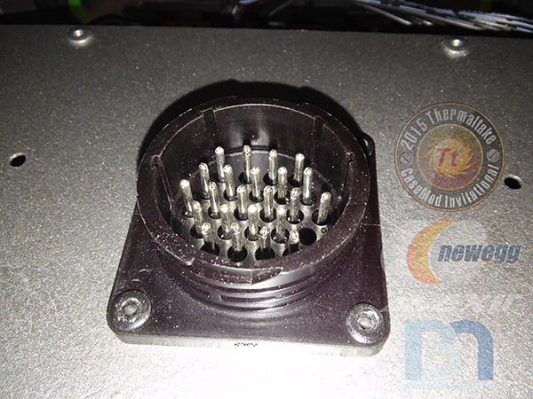
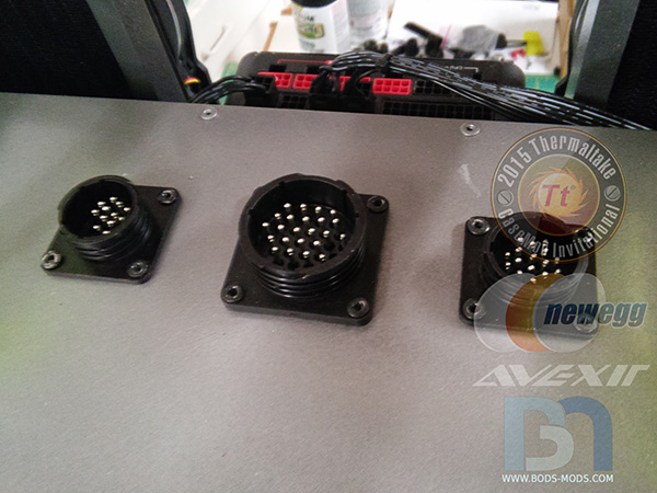
I wanted to make the inner chamber kind of a modular unit, so for the wiring I added industrial bulk wire plugs that screw into the box at the top.
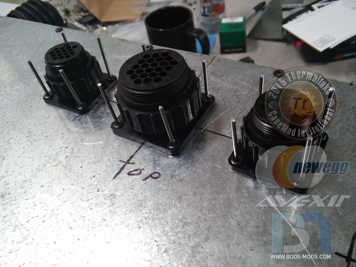
I actually found a 24-pin plug! I also grabbed a couple 16-pin plugs to use for the two 8-pin GPU cables and the 12v motherboard cables.

Here are the panel mount ends..
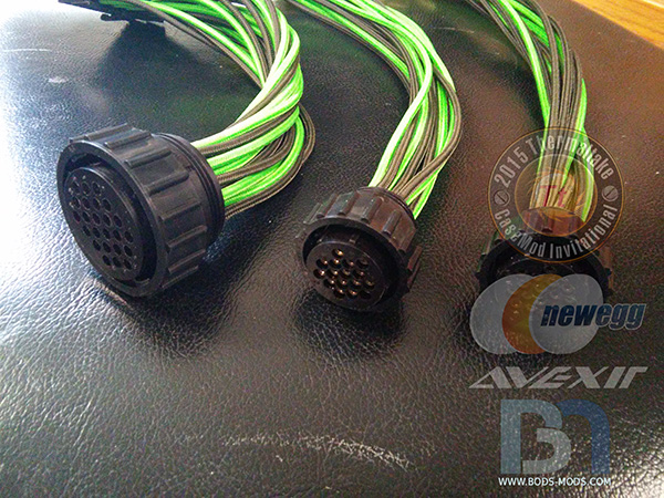
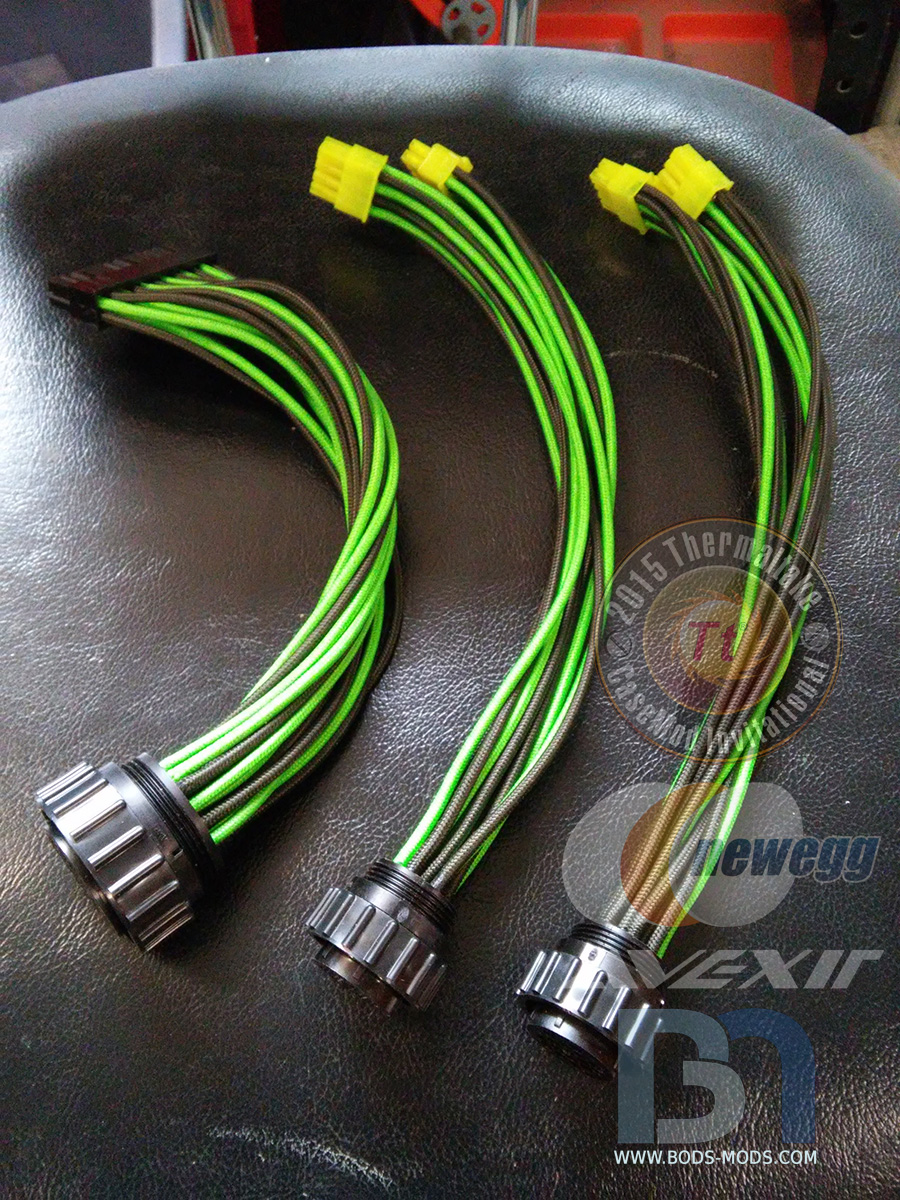
And here are the plug ends that have a collar that screws down to lock it in place.

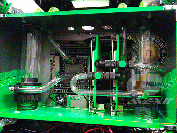
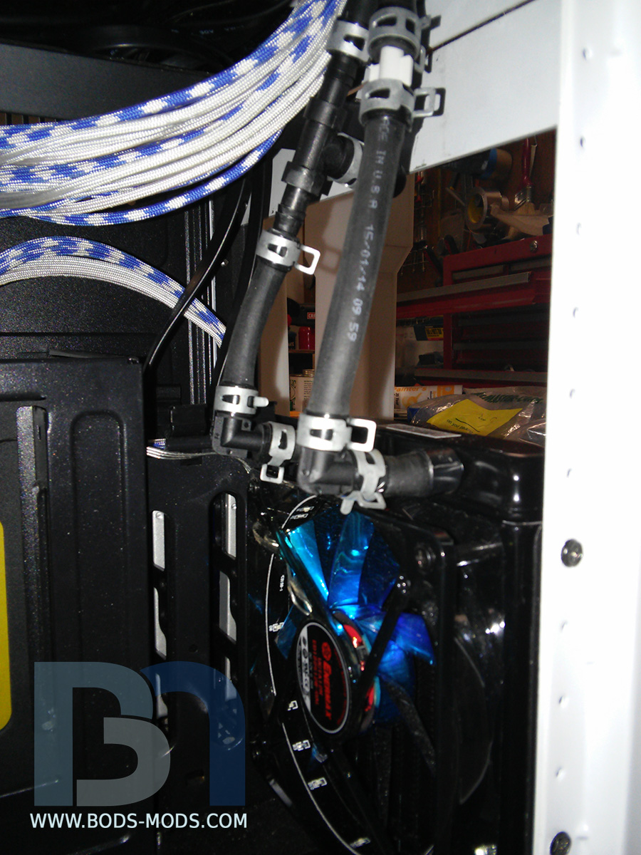
With that done, I could start working on running the hard line inside the box.
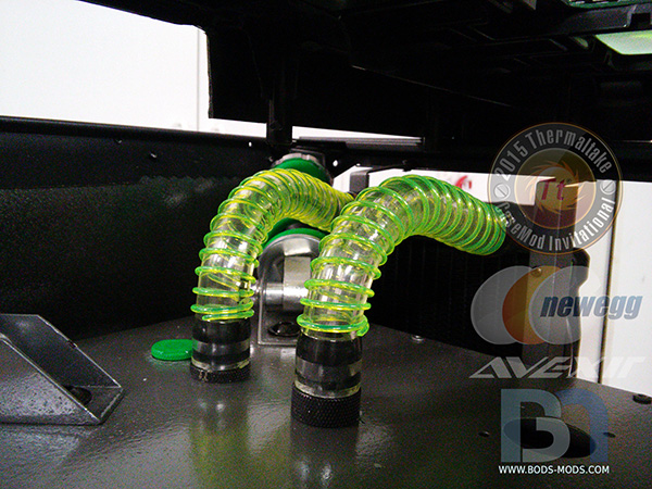
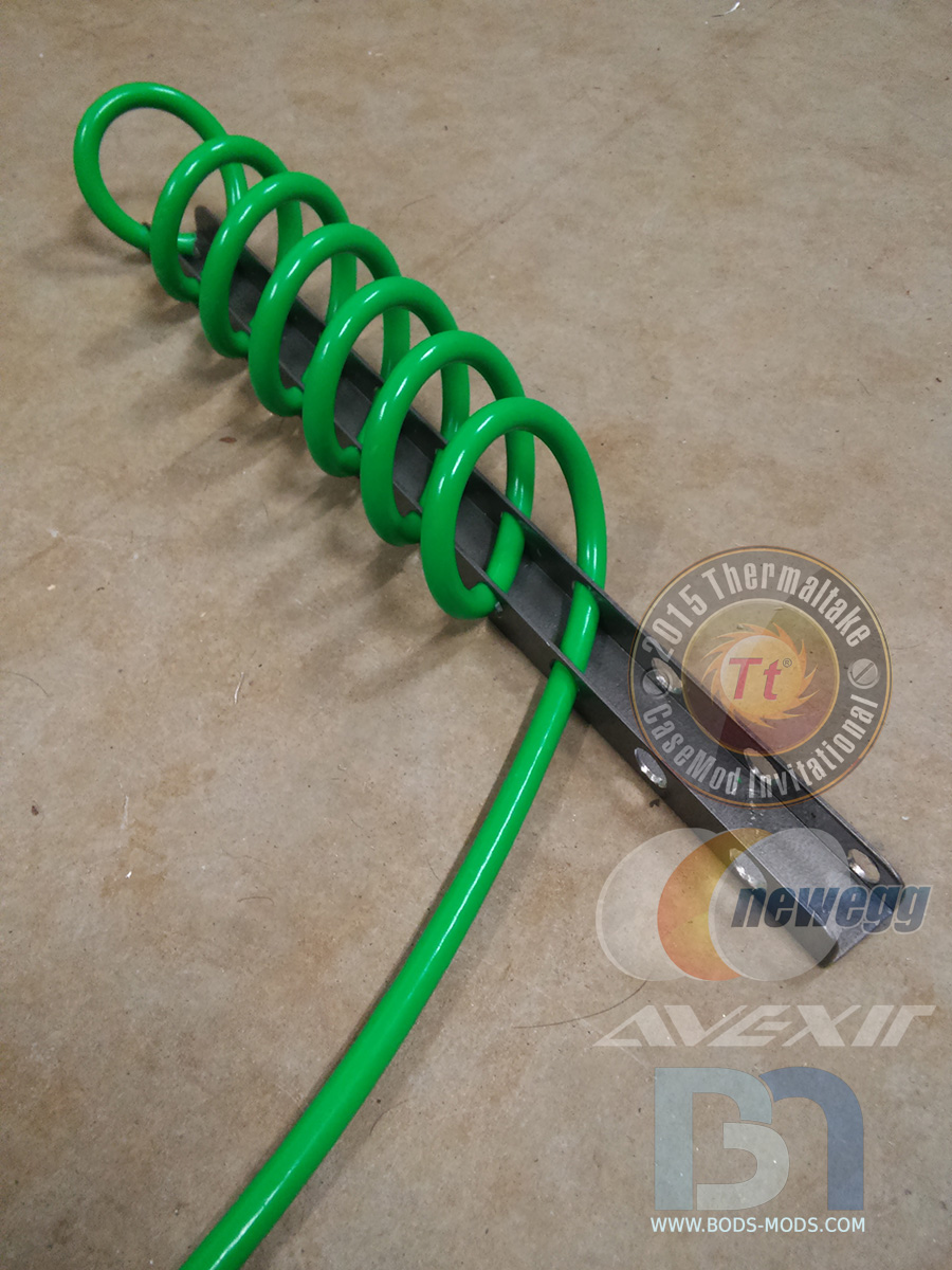
Being consistent with the theme, I went with flexible soft tube to go from the box to the rads. And I finally got to use my UV anti-kink coils!
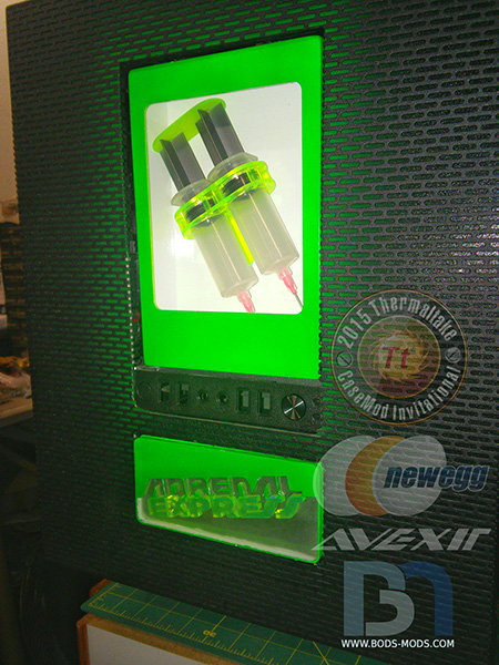
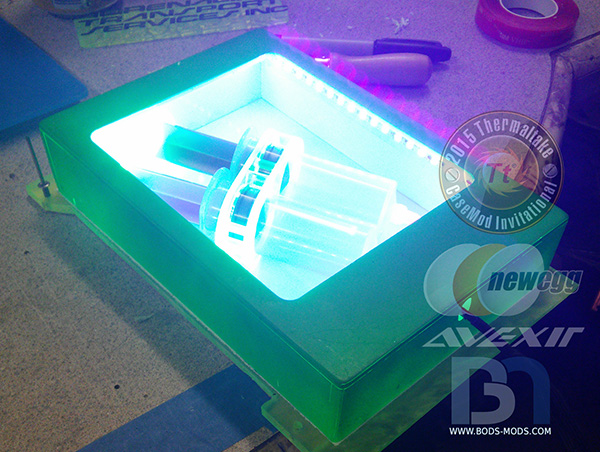
For the special front feature, I felt I had to include an emergency box, just in case someone was suddenly beset with a very bad case of the doldrums.
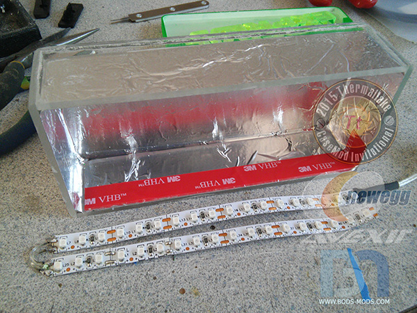
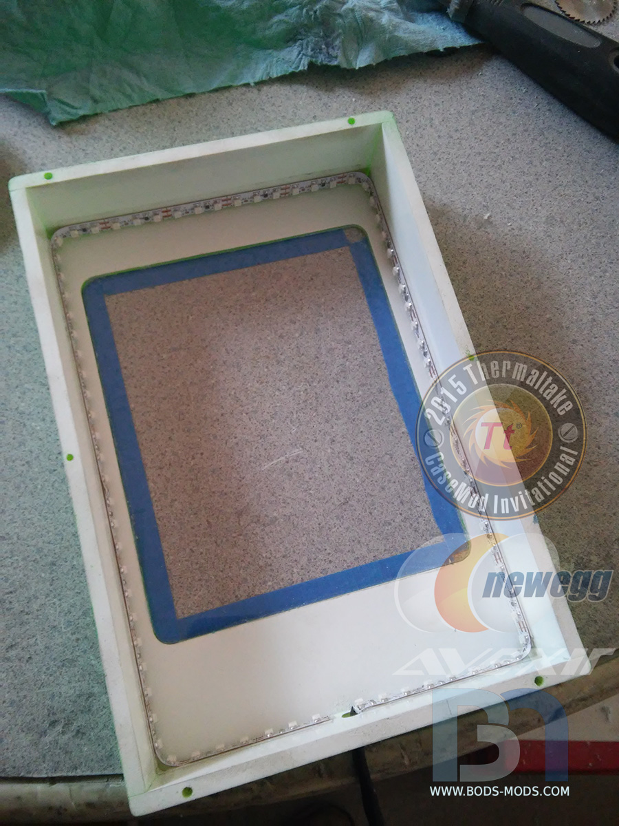
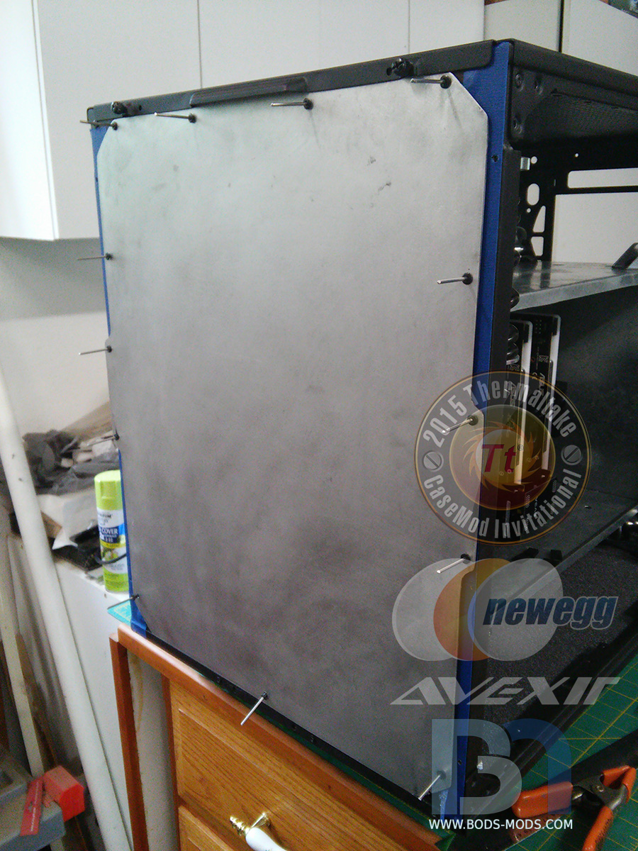
Here is the back side of the box I made from acrylic, painted white on the inside to reflect all the light from the UV ledstrip.

Testing the fit in the front panel. I made a custom dual syringe for that double-shot fix!
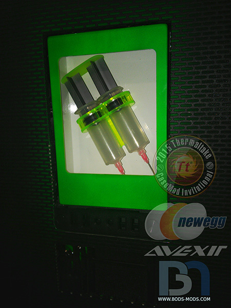
Testing the lighting..
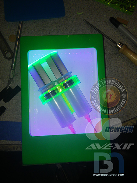
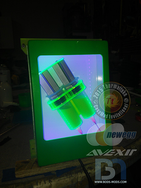
.. and filled with adrenaline..
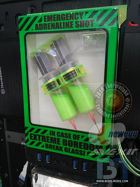
And finally, the finished box with the necessary messaging..
Final pics coming up next..
-
Thanks guys!
Had a great productive weekend, got a bunch of little things taken care of, and was able to start assembling the water cooling loop.
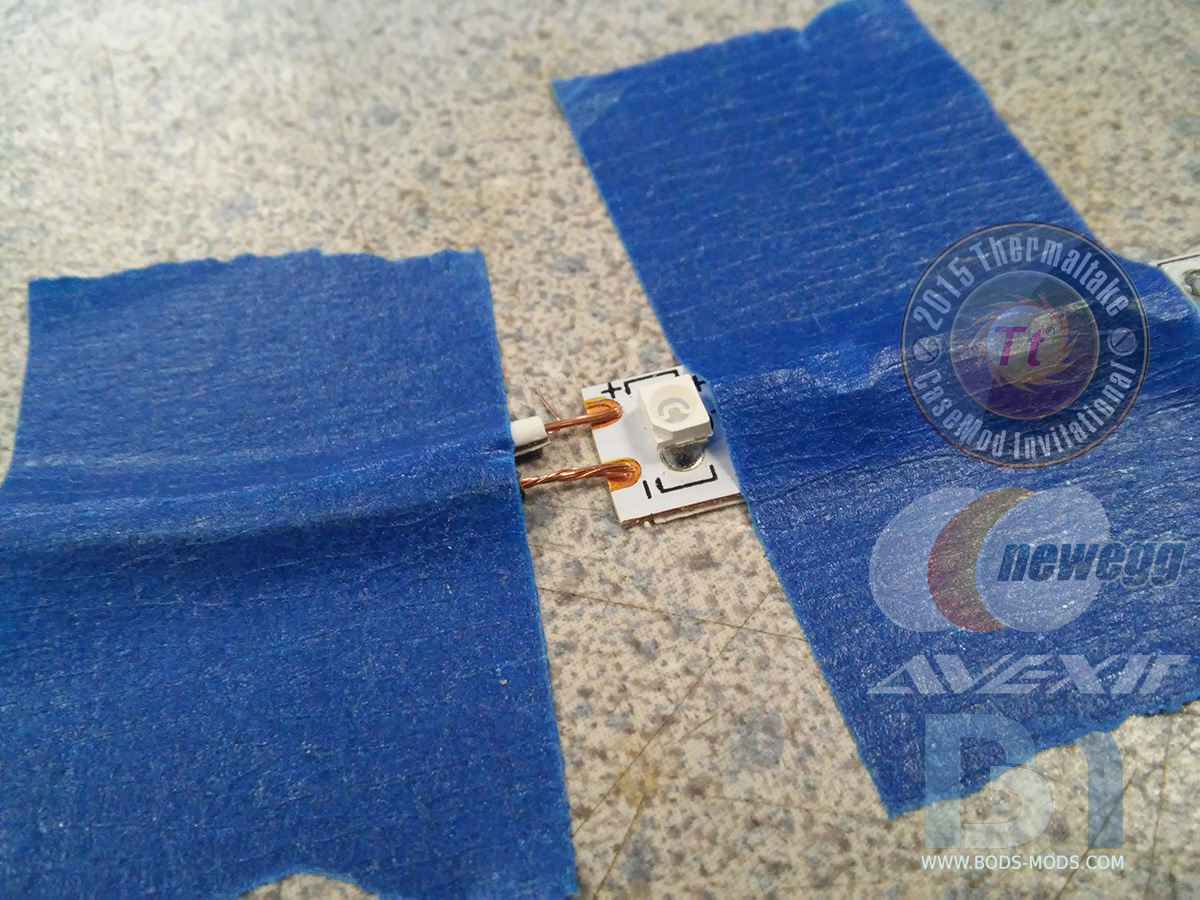
Got some of the lighting done, which required some soldering. I had to cut up the UV ledstrip and re-attach them so they would lay where I wanted.
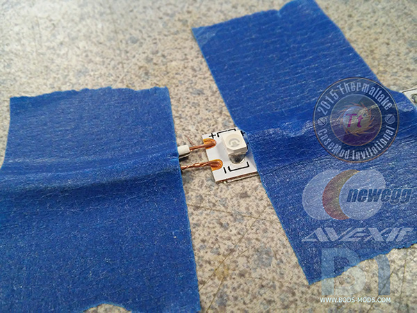
For the logo badging on the front, there was only a small area where I could hide the leds so they wouldn't bee seen through the badge, so two strips were laid side-by side and connected via two small wires.
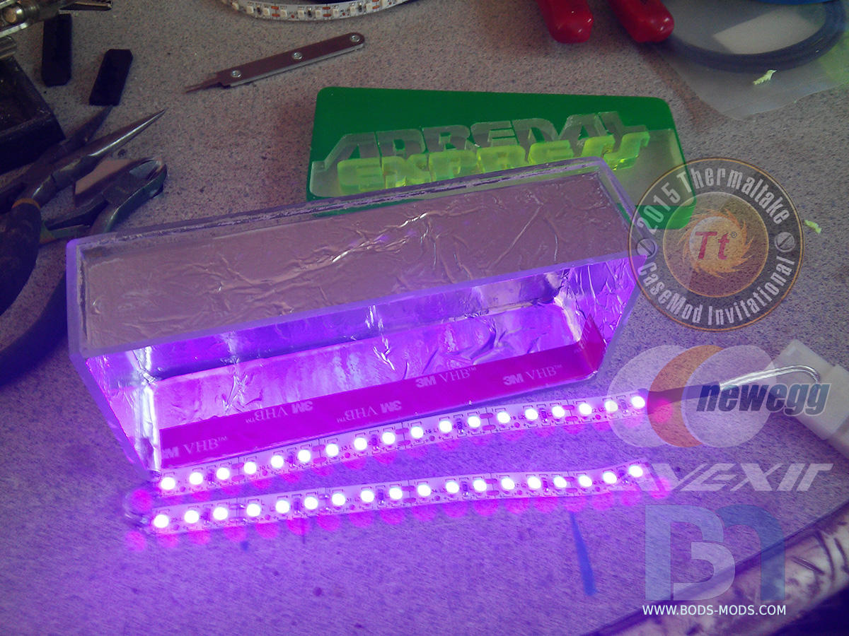
A quick smoke test..
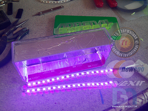
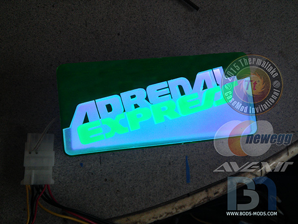
Once I confirmed they worked, I stuck them to the inside of the lightbox, on the wall behind the solid part of the logo. The box was lined with aluminum foil tape, which accomplishes two things: Reflectivity inside the box, and keeping the light from escaping anywhere else but out through the logo face.
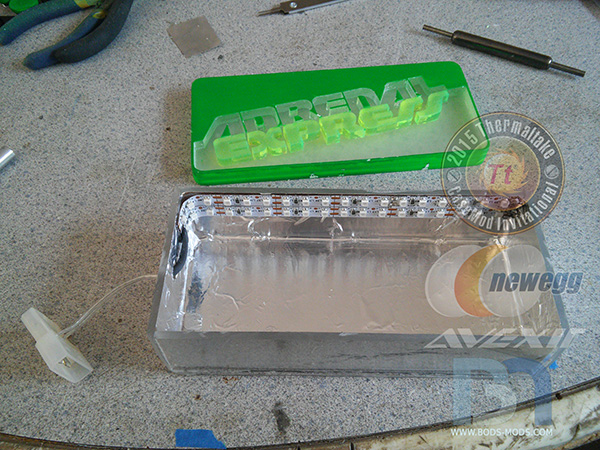
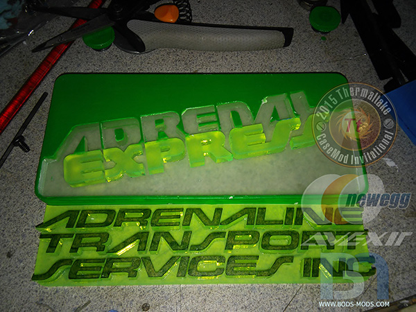
Here's the logo lit up with nice indirect lighting.

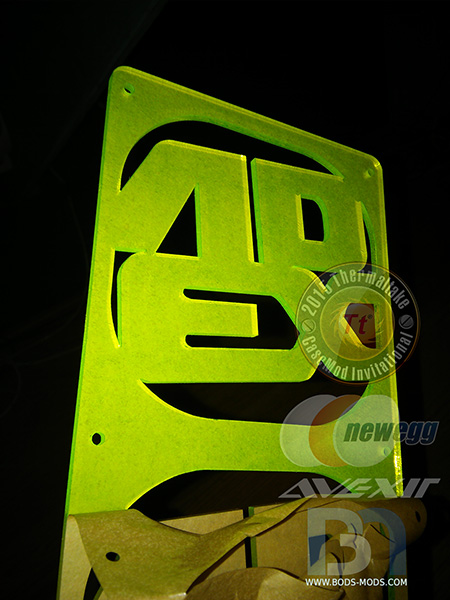
And here's the finished lettering that will go underneath the lit logo badge..
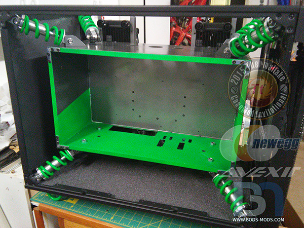
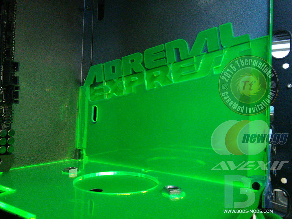
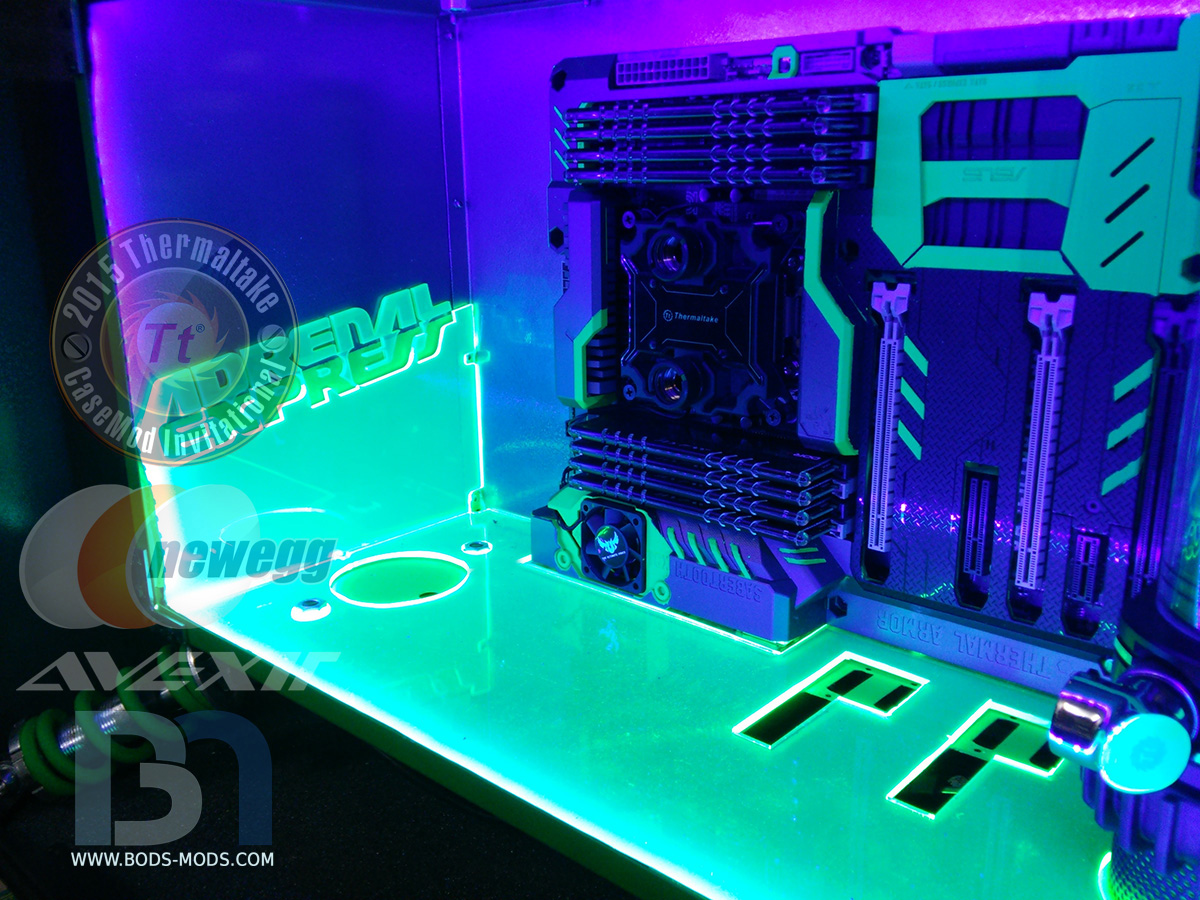
The logo also makes an appearance inside the inner chamber, on both sides. I had some 1/8" acrylic cut to cover the floor and up the sides, turning into Adrenal Express half way up.
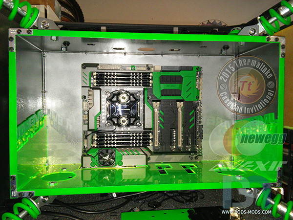
Now you know why I painted the inside of the box the way I did.

I got the box lit up with more UV lighting, hidden behind the front edge all the way around.
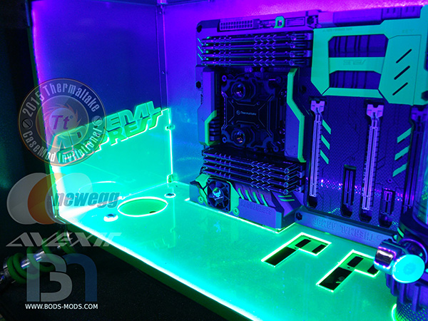
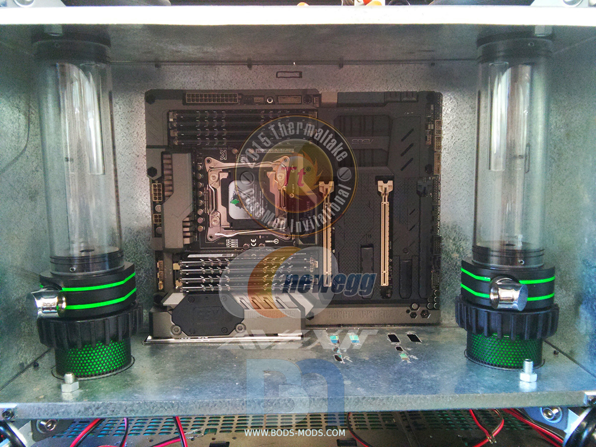
And finally with the floor in place, I could start installing reservoirs and the rest of the hardware..
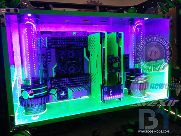
This is the last week before voting starts! It will be close, but I think I can get this thing wrapped up before the deadline. Wish me luck!
-
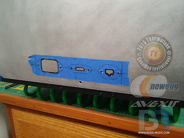
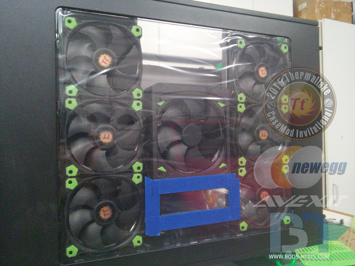
Got all the fan grills mounted last night. Both rads' fans and the PSU face the side panel, and sit right against the window. So holes were cut and the grills were attached right to the window.
First I marked all the holes on the window and taped off the area around the touch screen fan controller.
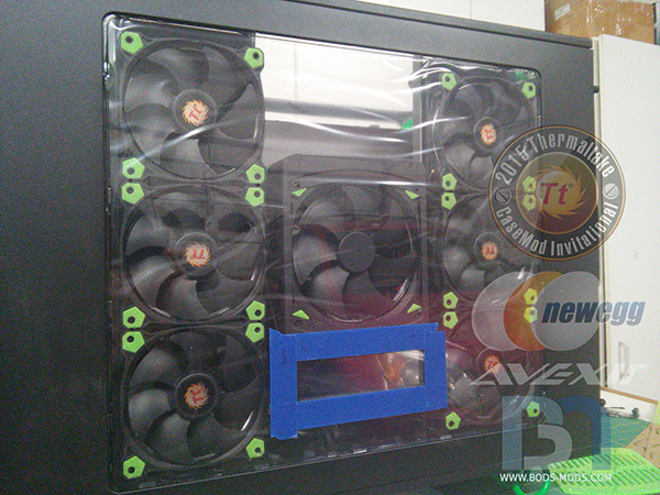
Then I proceeded to cut out all the holes after taping the surface for protection. This was after I cut everything and was demasking (forgot to take the pic earlier)
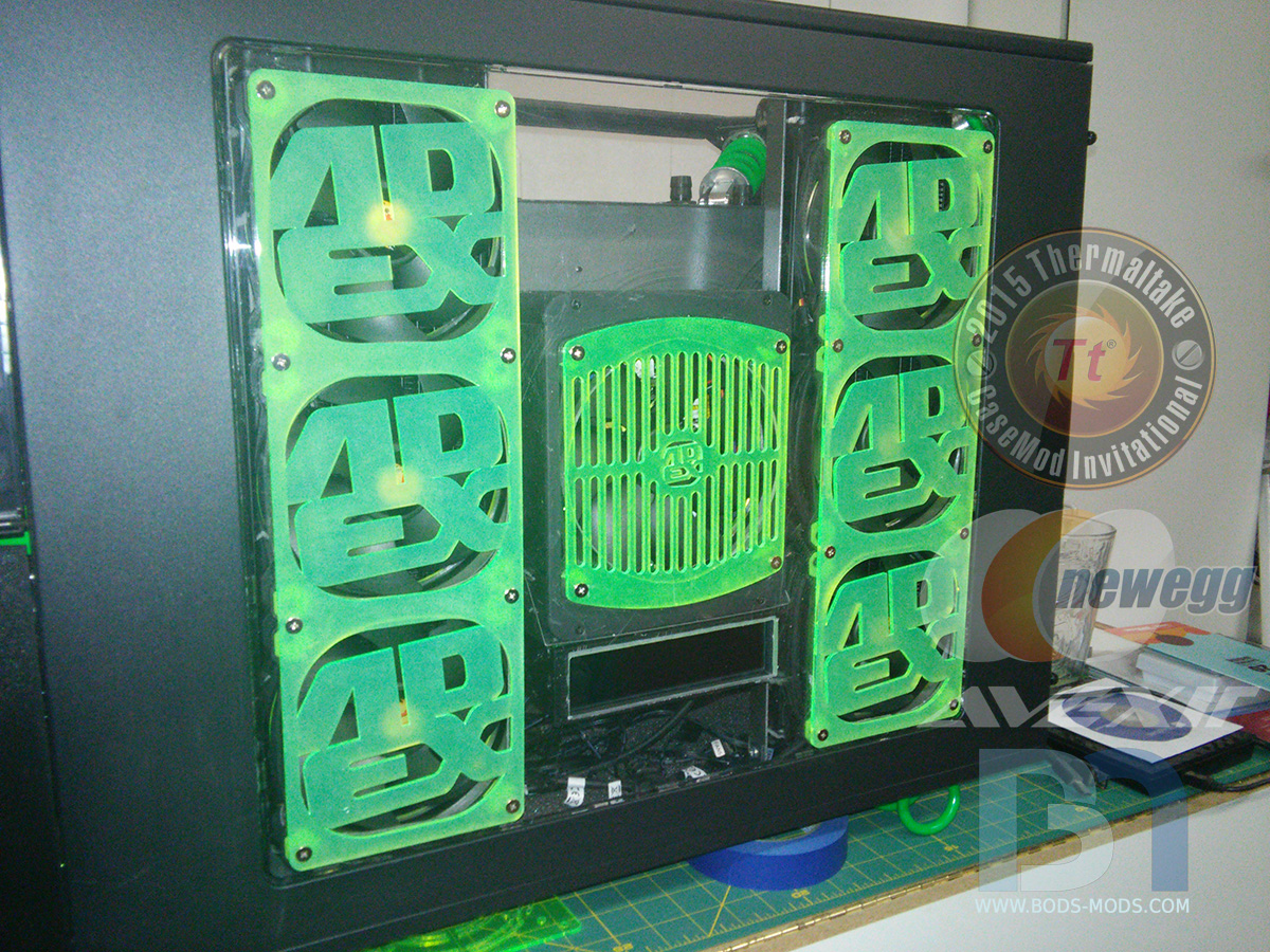
Testing the fitment of the rad grills.
After a light sanding of the grills to frost them up a bit, I mounted them to the window using spare HDD screws.

And the window back in the panel and on the case..
Looking forward to a good modding weekend ahead! Hoping to wrap up the front panel and get the pump/res's installed with tubing. Then it's on to wiring (ugh)
-
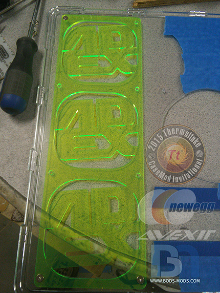
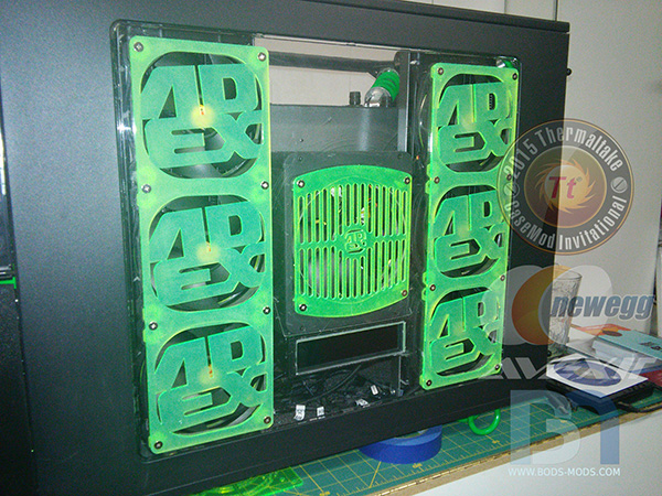
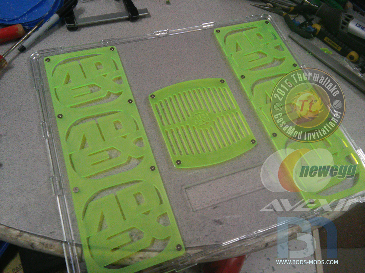
Got a bunch of things accomplished over the weekend. I got my laser cut acrylic in from Primochill on Friday, so my plans to do wiring got happily postponed lol. Here's a teaser shot of the radiator grills..
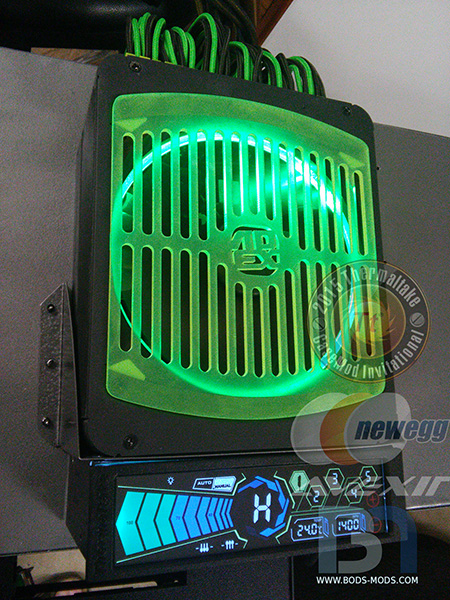
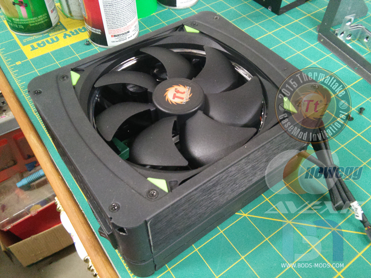
I remade the PSU's fan cover as well, with the Ad Ex logo in the center..
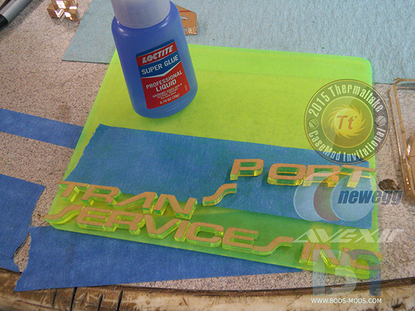
I will have a backlit logo badge on the front panel, so I had all these letters cut. It took a bit of time gluing all of them down. I used a piece of tape as my alignment to make sure everything was straight and spaced evenly.
I spent most of the time prepping the front panel for the logo badge and front IO relocation, as well as a secret special feature that I will reveal later. ;-)
I cut a piece of black ABS sheet to fit behind the mesh, and sprayed a bit of green around the cutout for effect. I'll be doing the same behind the top panel.
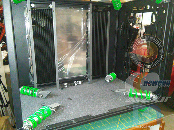
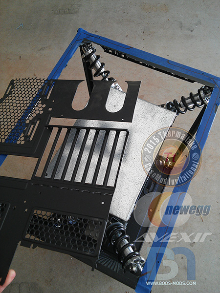
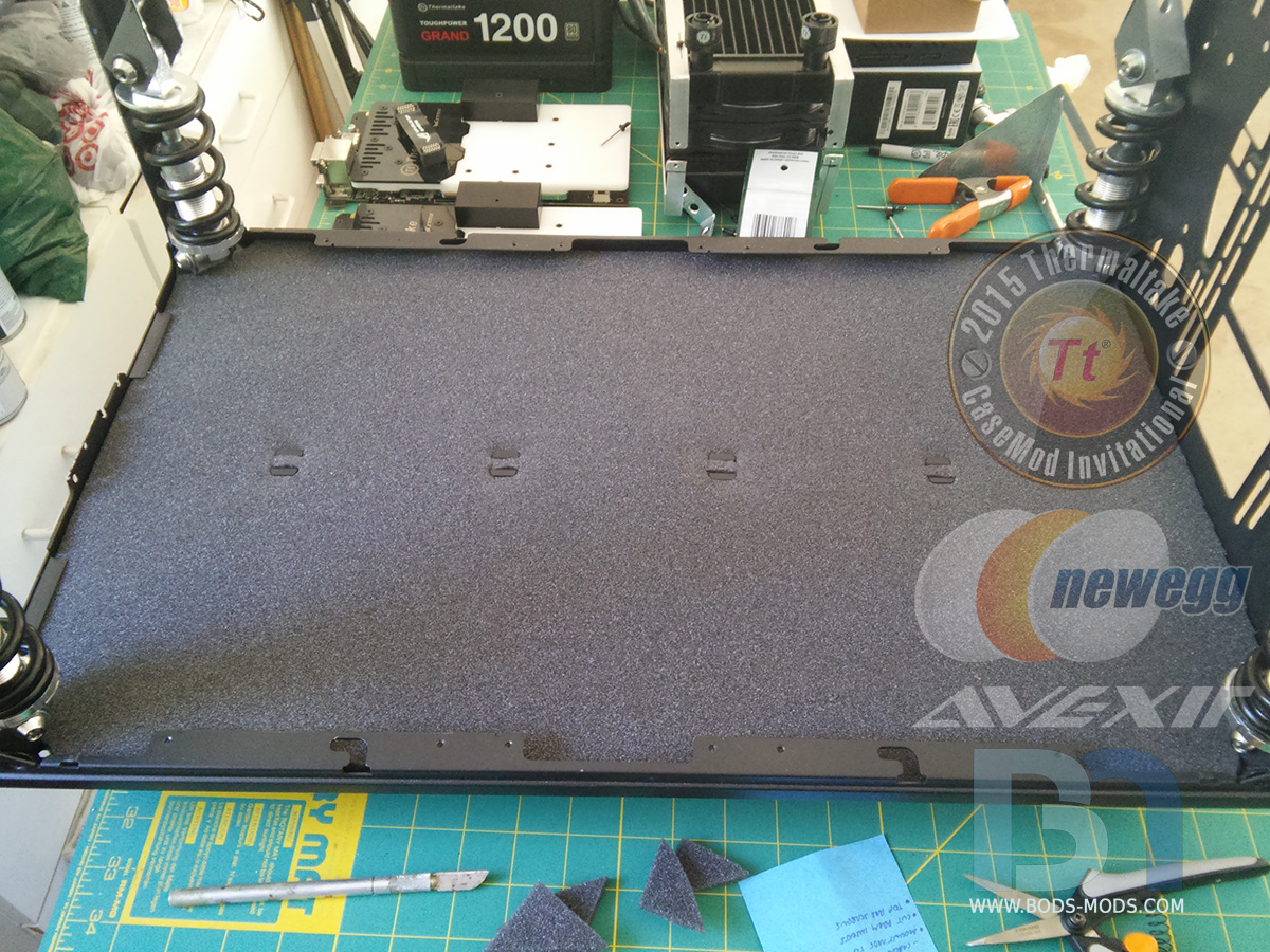
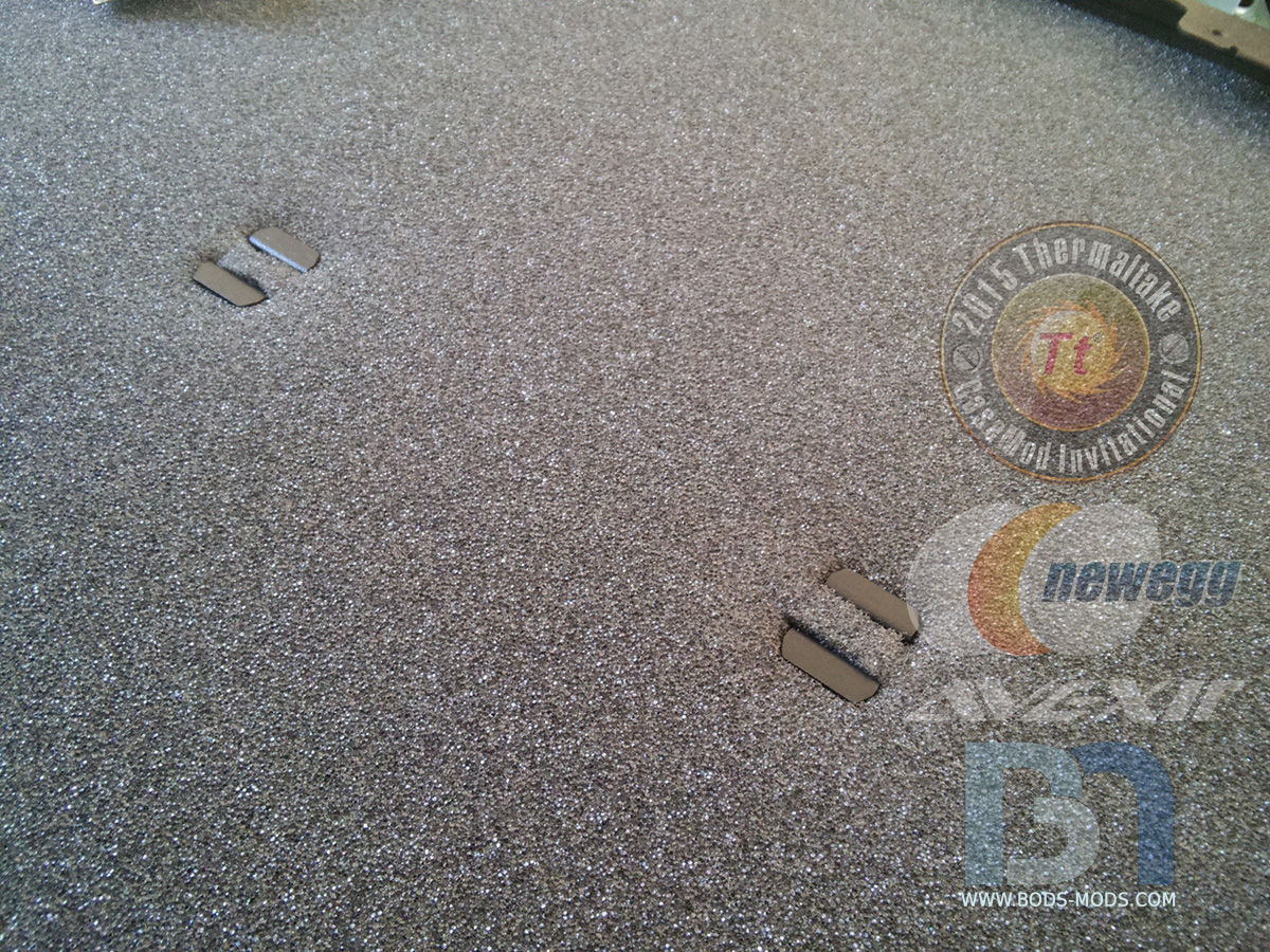
Before installing the inner chamber for the final time, I laid down some 1/4" foam sheet to cover the bottom of the case.

I cut some slots in the center to clear the dust screen hooks. They actually served to hold foam the down quite nicely.

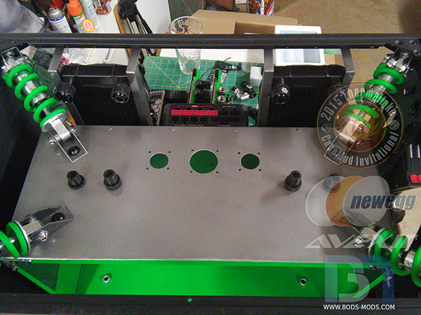
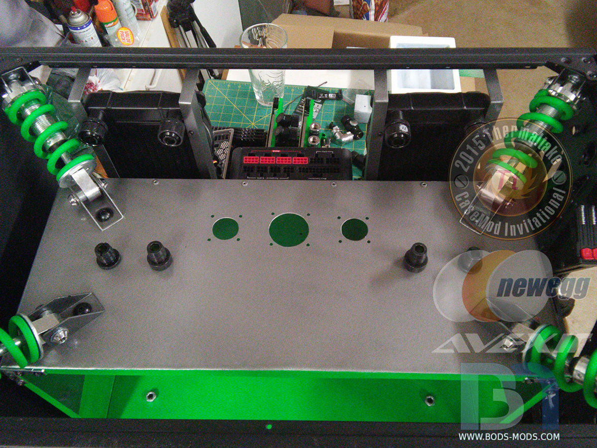
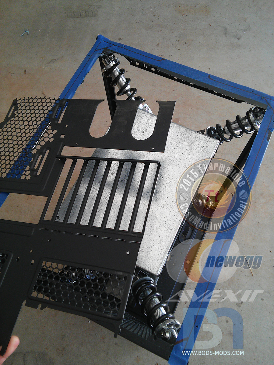
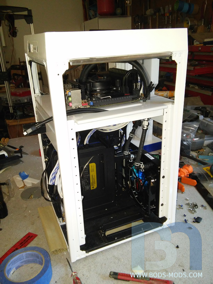
Getting the rads mounted, and all the shocks back in in preparation for the inner chamber.
The inner chamber is back in! Hopefully for the last time.
A shot of the top, with the WC inlets and outlets that will connect to the radiators.
- AlShuryan and JustinMern
-
 2
2
-
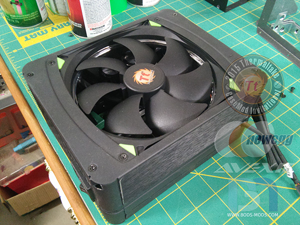
Finished the PSU last night, thanks to Shannon for sending me a 140mm green Riing fan.
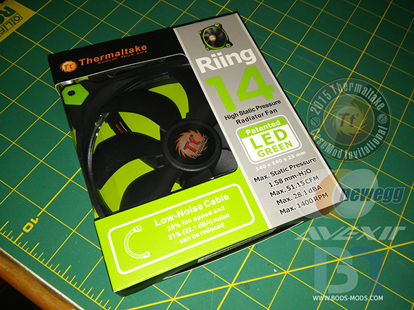
Installed into the PSU. The stock fan connector is only 2pin, so I'll have to run the new fan's cable out of the PSU and into the fan controller... which will be mounted directly underneath.
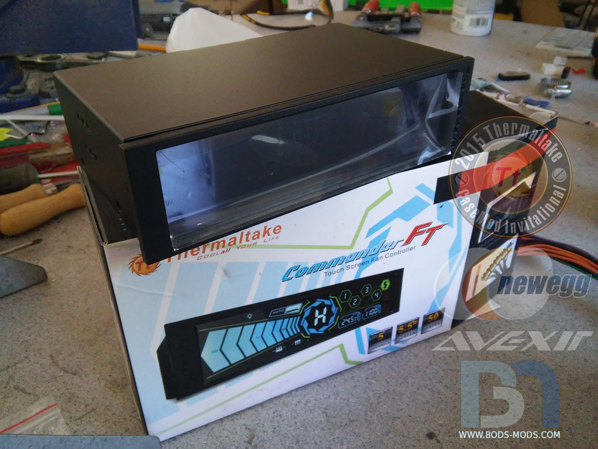
Speaking of which, here is the Commander FT..

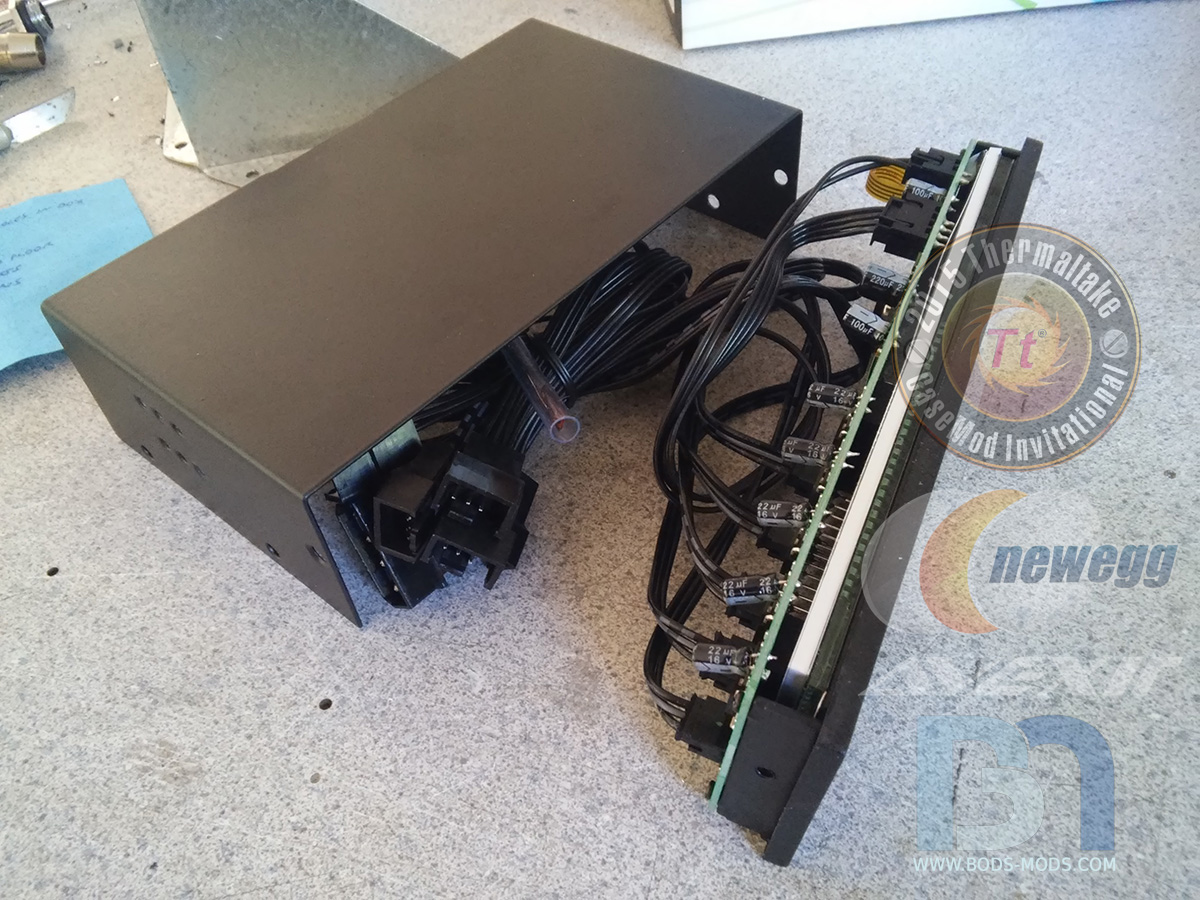
Removing the 5 1/4" mounting bracket..

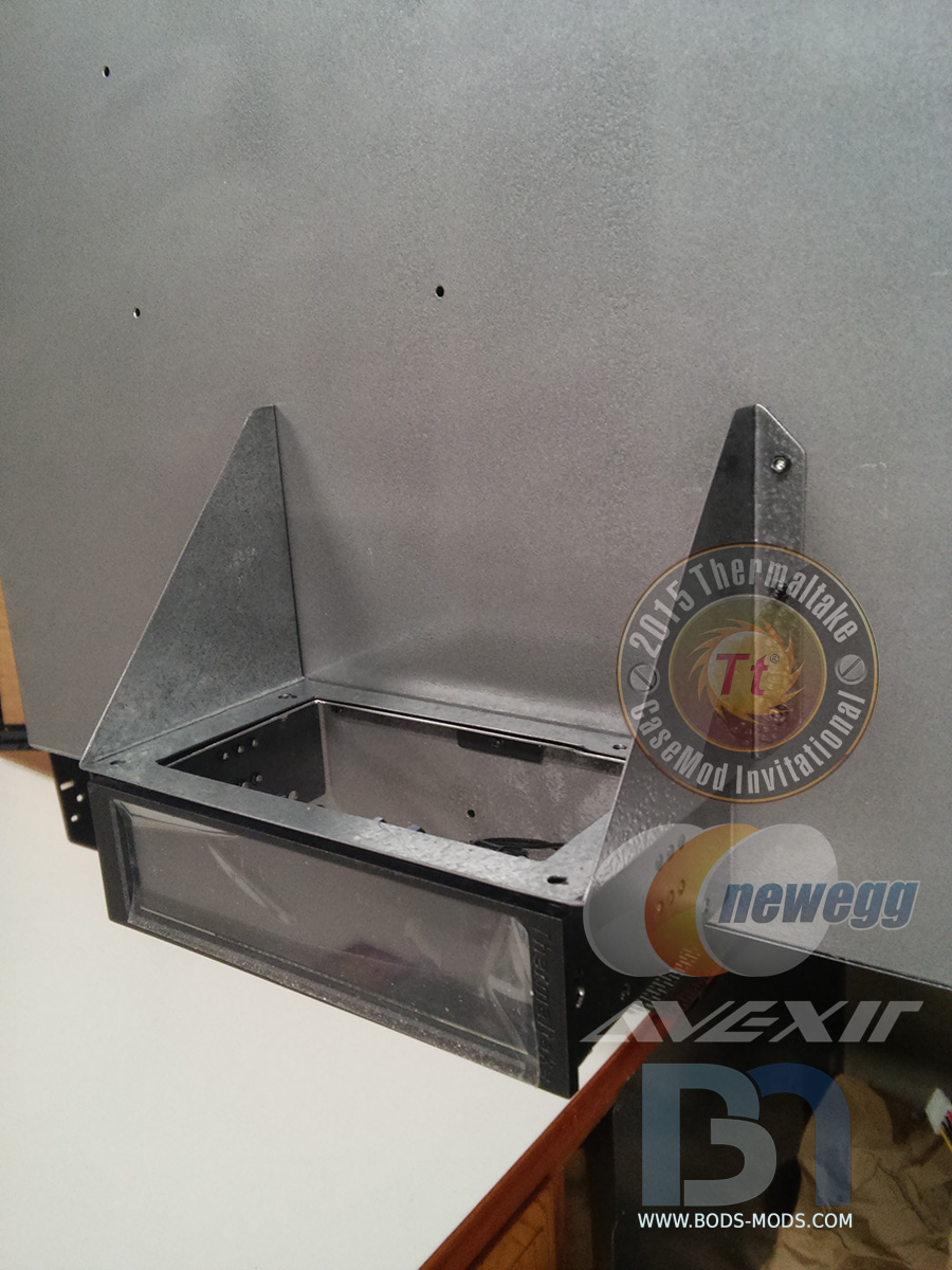
..and mounting it directly to the PSU mounting tray.
Now that everything is painted, I can finally mount the PSU tray permanently to the back of the inner box.
Then the fan controller bracket goes on, after cutting a matching hole in the top to clear the psu.

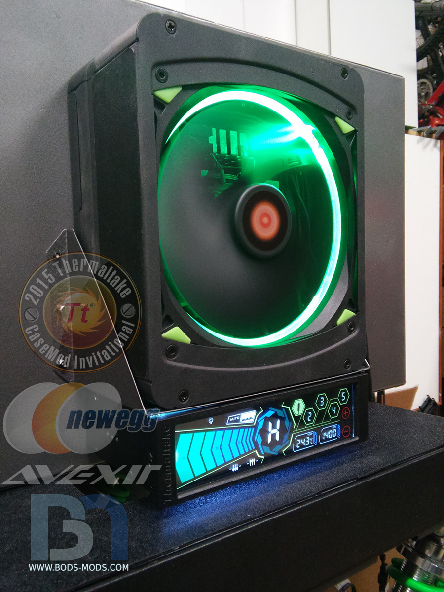
PSU and fan controller installed.
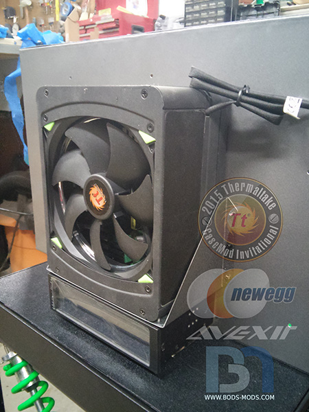
Plugged in for a test run..
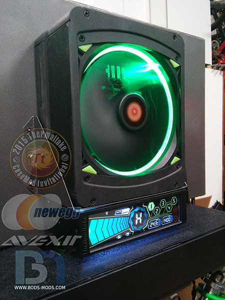
It's all starting to take shape now!
-
Great detailing on the sabertooth cover! Just the right amount of color I think.
I have the same board, and am presently working on adding neon green accents to mine. You are lucky the blocks on the video cards are already white! I will have to paint mine to match my color scheme. Keep up the great work! -
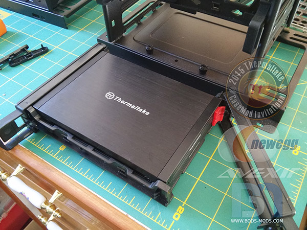
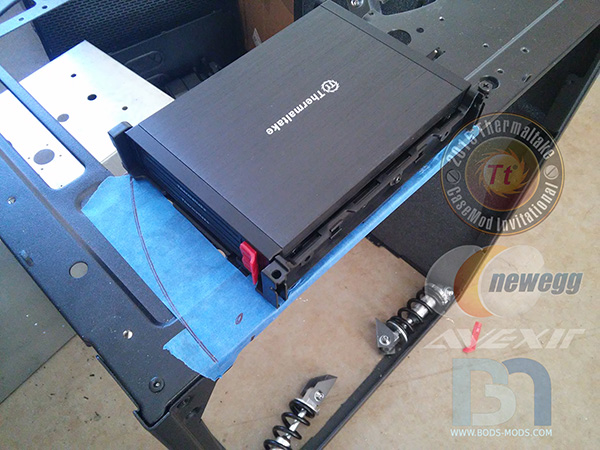
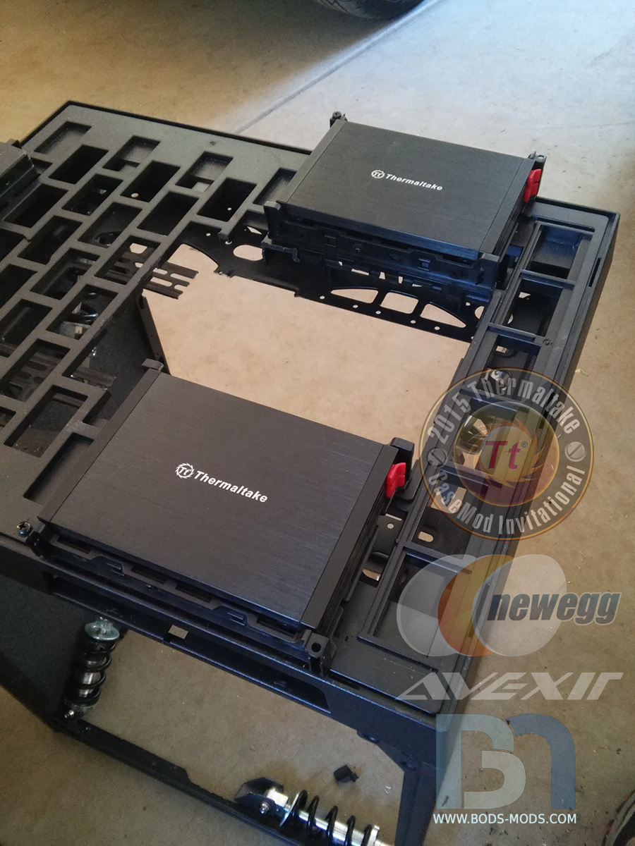
The last bit of fabrication I had to do involved placing the 2 Max5 Duet HDD Racks. They will be hidden inside the front bezel, but still easily accessible for hot-swapping the SSDs.
Here's how they will be positioned, one on each side.

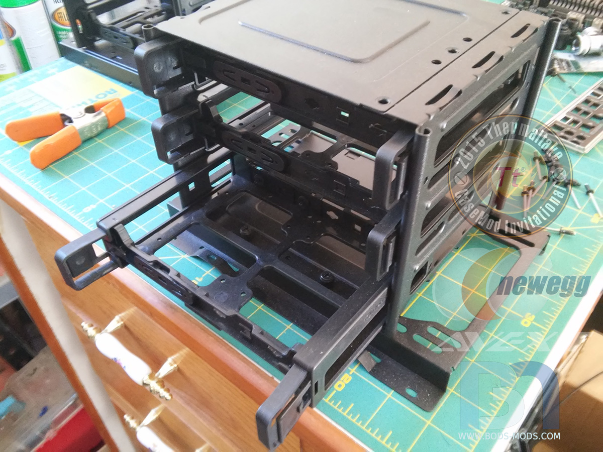
I'm always looking for ways to re-incorporate parts of the original case into my designs. These hard drive racks will be perfect for mounting the Duets!

They fit like a glove inside the tray..
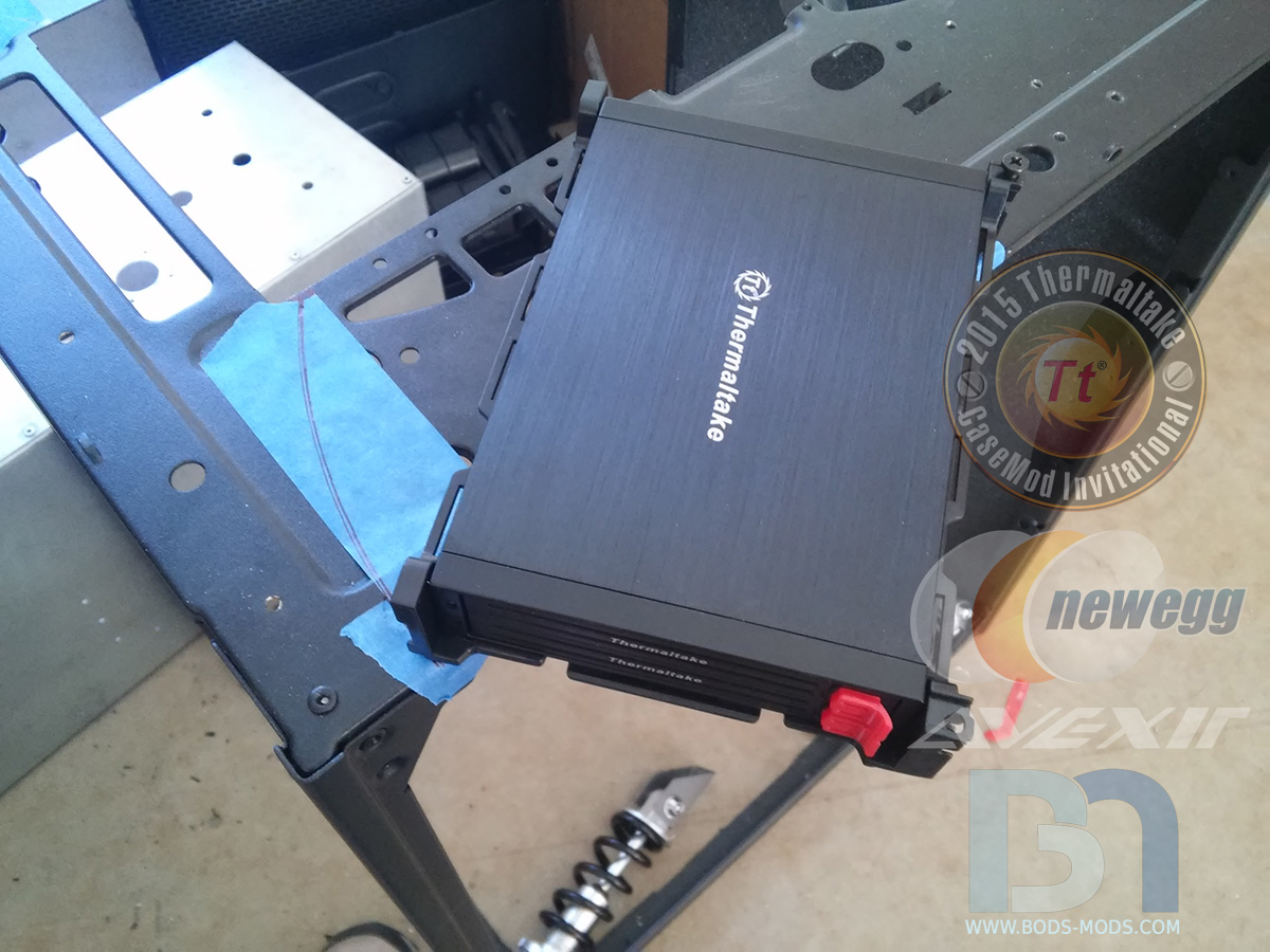
I won't be needing the doors, but will be utilizing one of the hinge points, so the tray will pivot out the side of the front bezel. I scribed an arc showing the drive's travel from closed..
..to the open position.

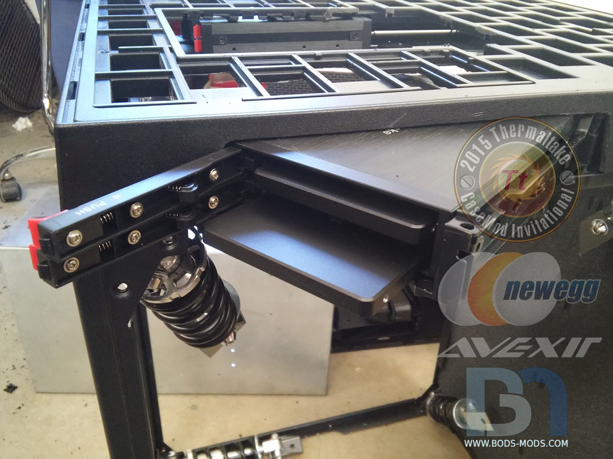
After removing a bunch of material from the underside of the front bezel, the drive racks are now clear and can move freely. The bezel already has openings on the side, originally meant for the power/reset/audio panel, but the holes still needed to be widened a bit.
Now the drive rack can be pulled out fully, and the SSD's accessed easily.

Now that all the fab work is pretty much done, I can move on to paint!
-
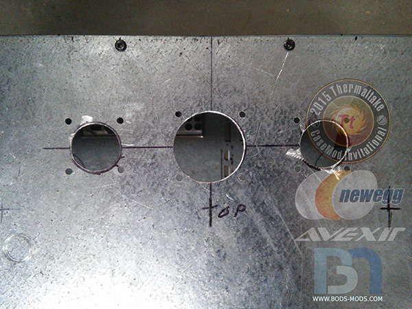
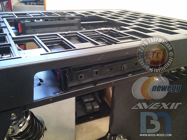
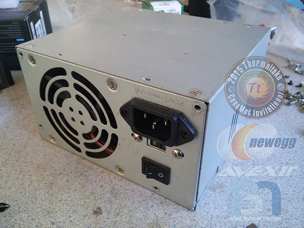
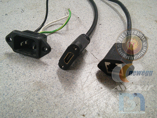
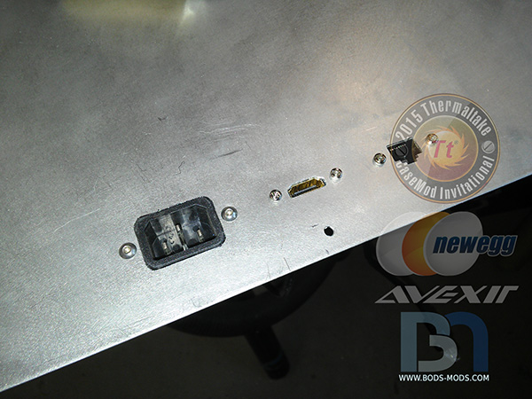
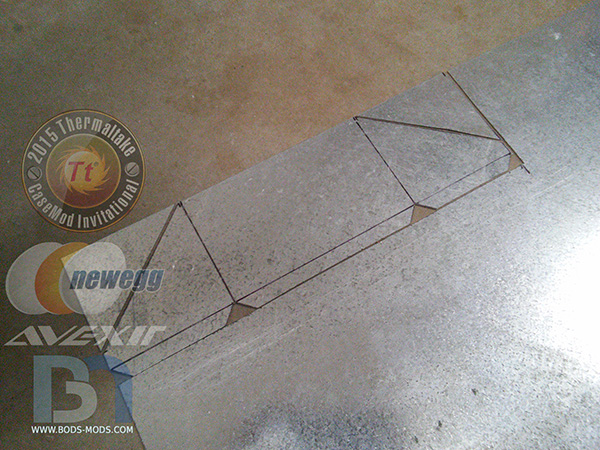
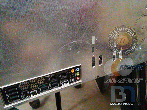
Since the motherboard is mounted in the inner chamber with the IO facing down, I'll be using some panel mount extensions for HDMI, ethernet, and power connectivity.
First, I pilfered the power plug out of this old psu
I found the HDMI and ethernet panel mount extensions online.
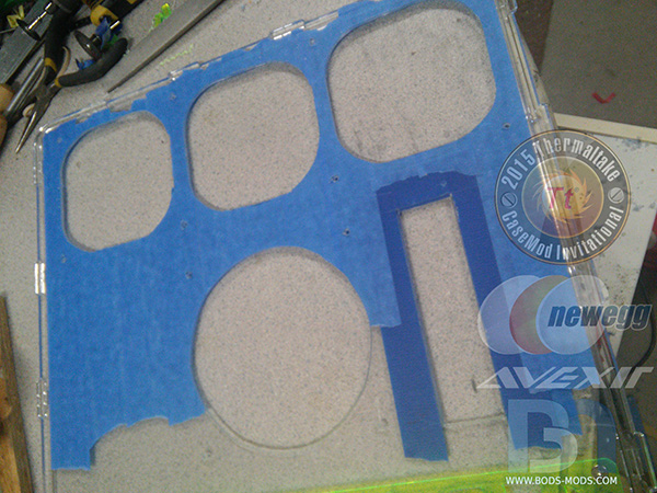
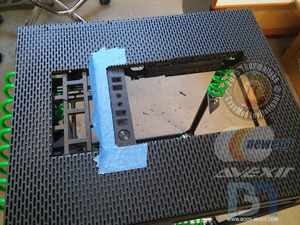
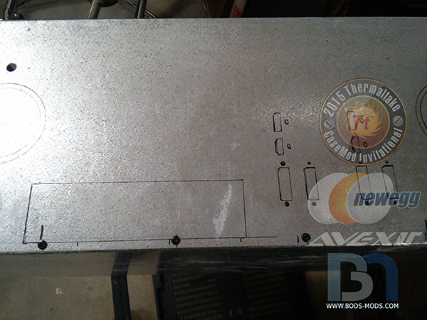
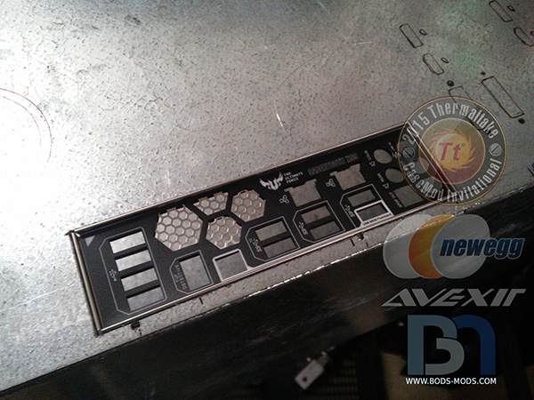
Here is the new back panel I made to replace the swiss cheese that was there before.

Using the panel mount ends, I made myself a template on tape and transferred it onto the new back panel.
After removing material and some filing, the panel mounts fit nicely at the bottom center of the back panel.
Getting down to the last couple items I need to fabricate mounts for, then it's time for paint! Stay tuned..
-
Looking sick Brian..Always love your work .I hope you win this thing!!
Thanks Ron, but I will be hard pressed to beat your steampunk insanity, or any of the other builds! Everyone is doing such a terrific job it will be difficult to pick a winner I think.
-
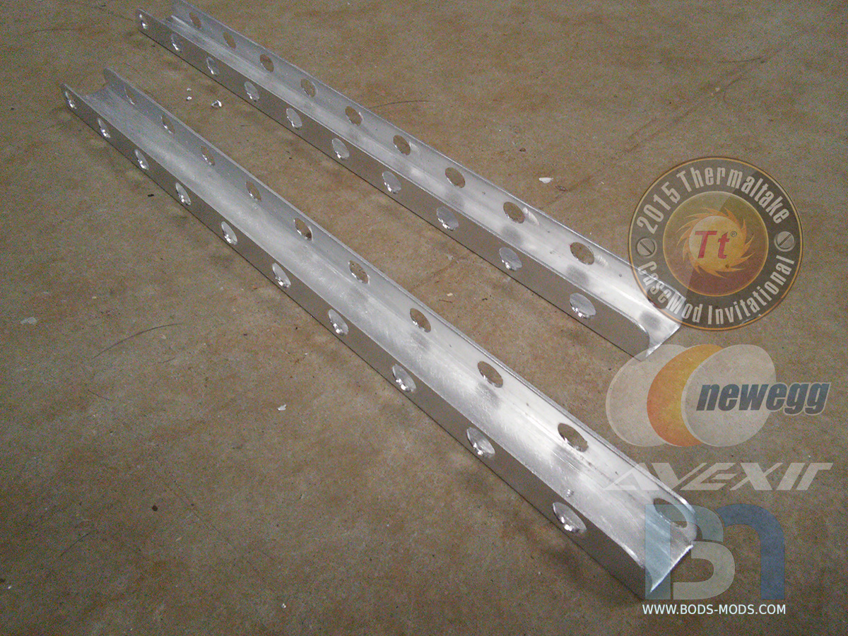
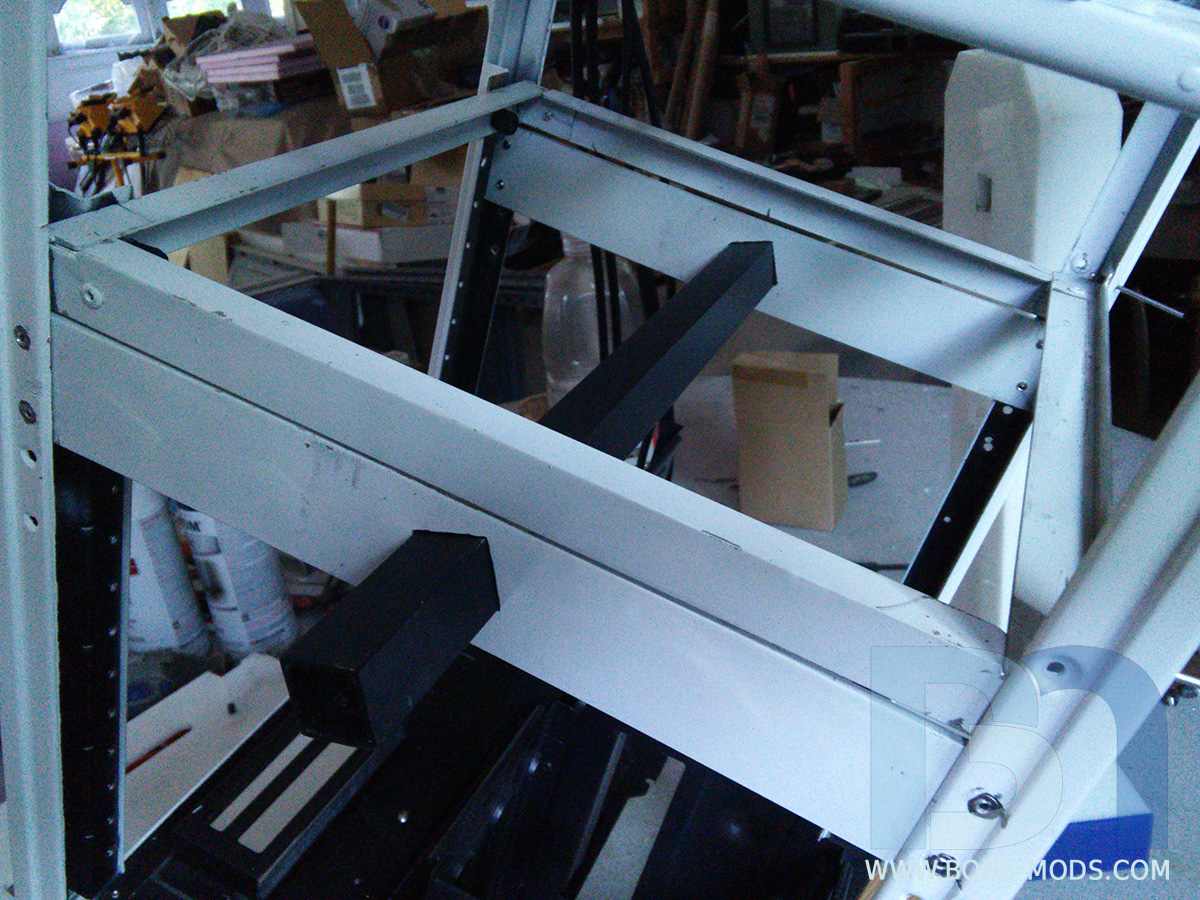
More chassis modifications were necessary to ensure the safe and secure delivery of this most unpredictable substance. After exhaustive stress testing with premenstrual gorillas, extra care and stabilization was duly recommended, and therefore additional anti-vibration spring rails were employed at the base of the container.
Fabricated simply from C channel and 1/4" multi-strand cable..
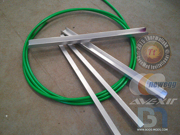
Pass-through holes were drilled into both sides of the C channel.
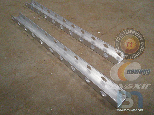
Once painted, the cable was threaded through.
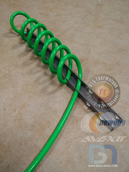
Both rails complete!
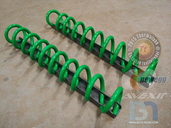
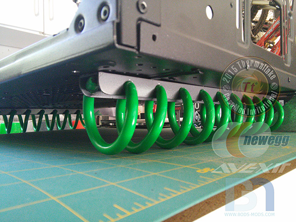
Inverted and mounted to the case. It was decided that there was no need for the extra 1/4" bar seen in the first pic..
-
I'm loving the detail man. That back panel is insane already! Looking forward to the finished piece!
-
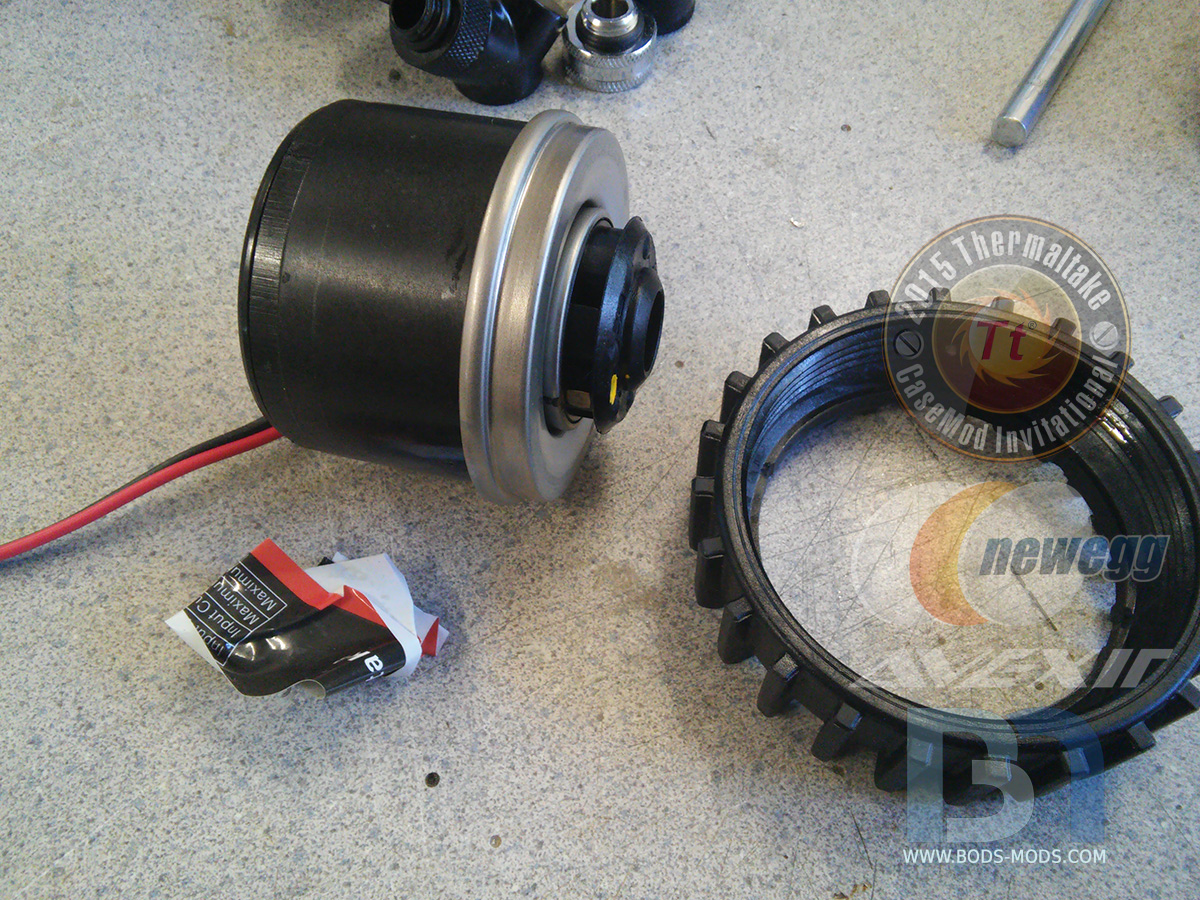
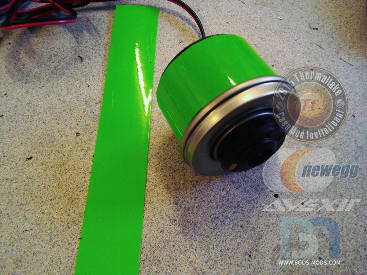
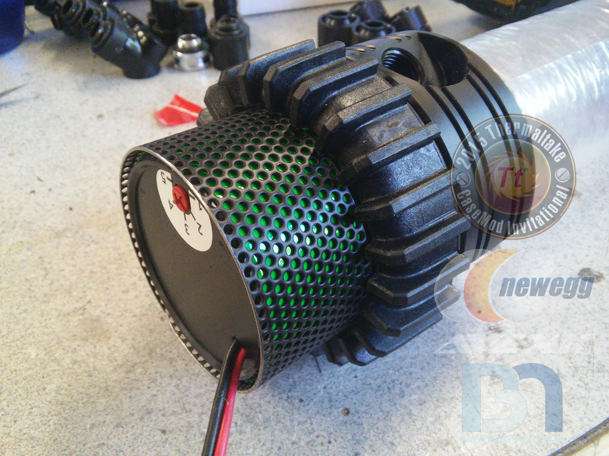
This vessel will be carrying the potent adrenaline, so it needs to be very strong and impervious to cracking, crazing, scratches, bullets, lasers, sharks, ... and even laser sharks. And since there is nothing tangible on this earth presently that comes close to this, I had to travel into the future and bring back some transparent unobtanium. Fortunately, I found that the future Pringles chip containers were made of it and happened to be the exact sized cylinders I needed, and was able to purchase a couple cans from the local Eleventy-Seven (formerly known as 7-11).
Here's the stock container, ready to be upgraded.
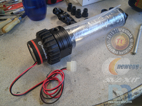
The de-agitator was disassembled, and it's feeble exo-coating removed.
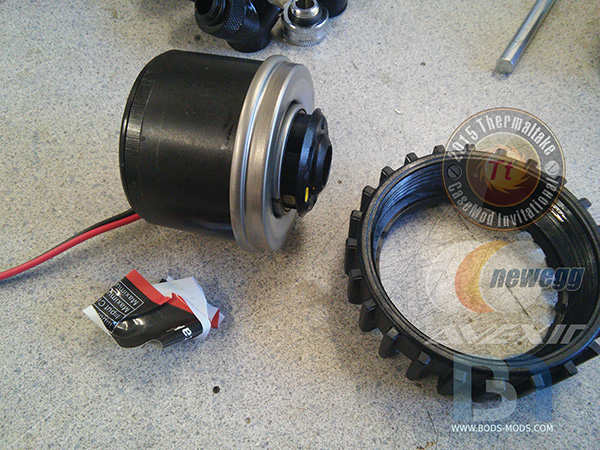
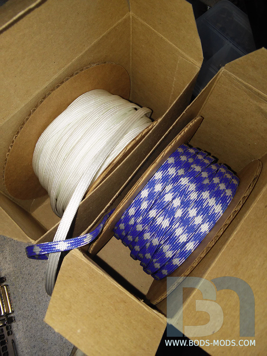
A special protective UltraViolet-activated barrier strip was applied to the outside.

To further dissipate all those UltraViolets, this semi-permeable alloy was added over top the barrier strips.
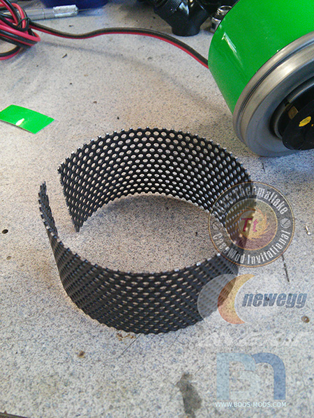

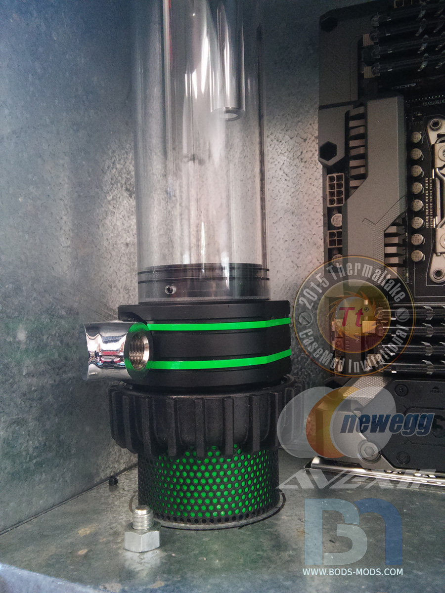
Once, reassembled, the housing's performance is greatly enhanced by these super cool racing stripes..

Both vessels have been upgraded, and ready to be filled with the toxic fluid.

-
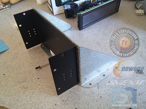
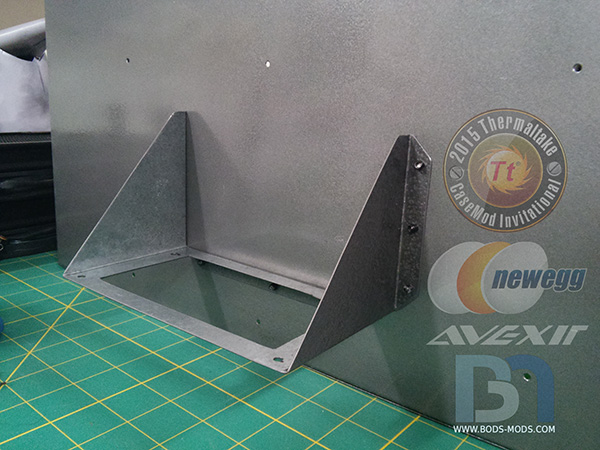
The power supply will be located on the back of the inner chamber, in between the two reservoirs. But in order to mount it there, I'll need to fabricate a bracket for it to sit on. So more galvanized steel was cut..
..and bent into a shelf-like form..

..Here's a couple shelfies..


The mounting holes were transferred to the bottom panel from the psu itself.
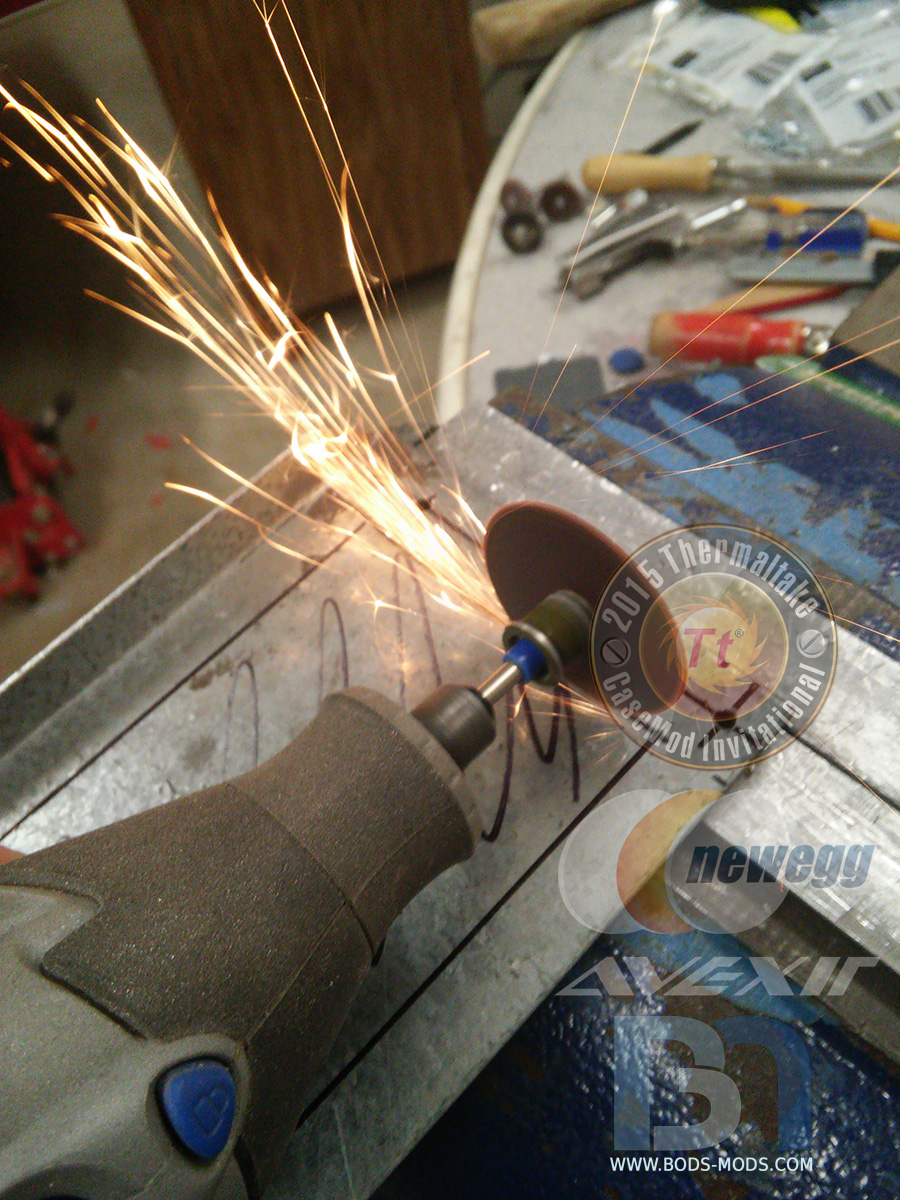
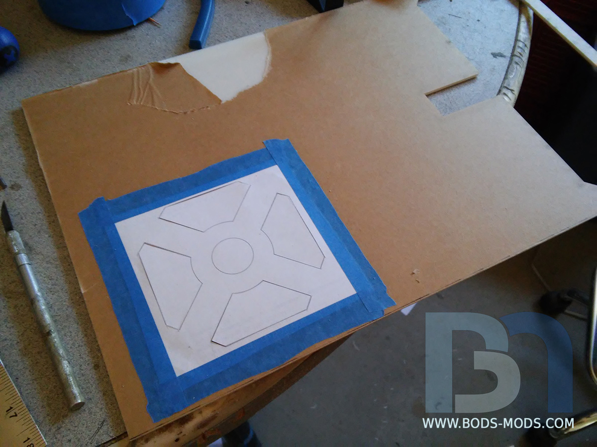
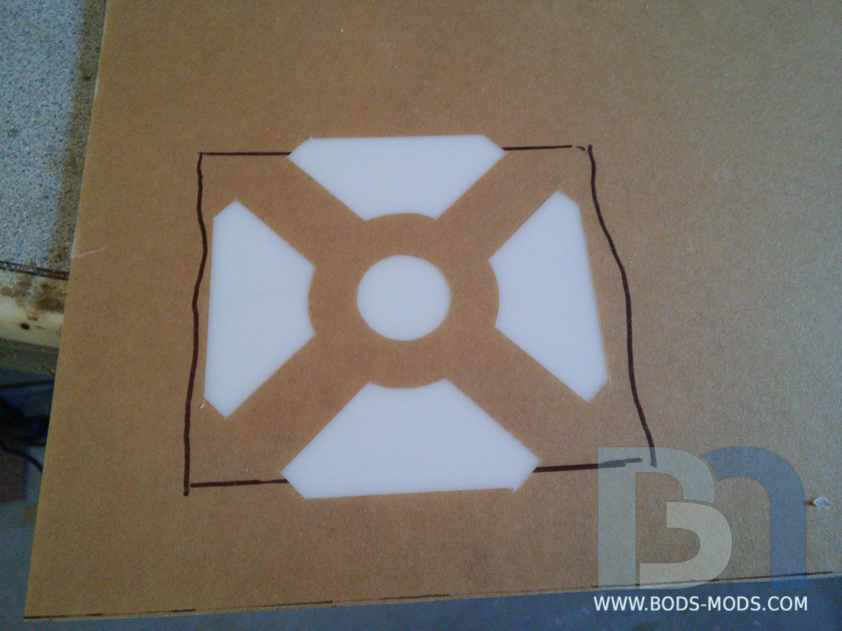
Using special diamond-carbide cutting wheels, I was able to remove the center of the panel for adequate PSU ventilation.

And the PSU mounted to the shelf.
Using a box, I propped up the PSU and shelf to the desired height so I could mark the holes on the inner chamber. It will be held in place by some pop rivets once everything is prepped and painted and ready for final assembly.
- hotcoolman and Richi
-
2
-
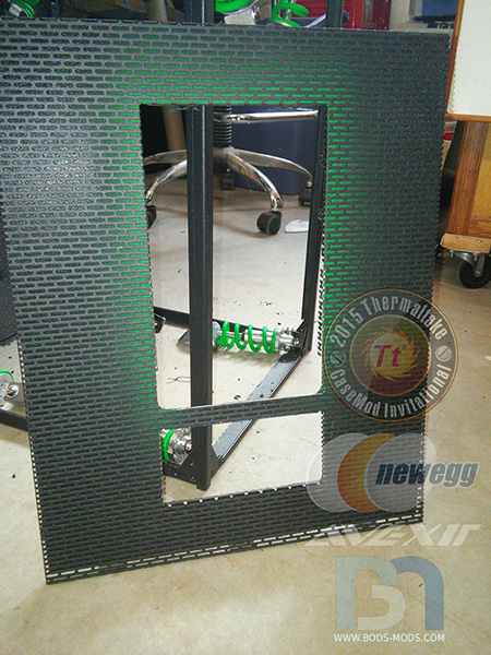
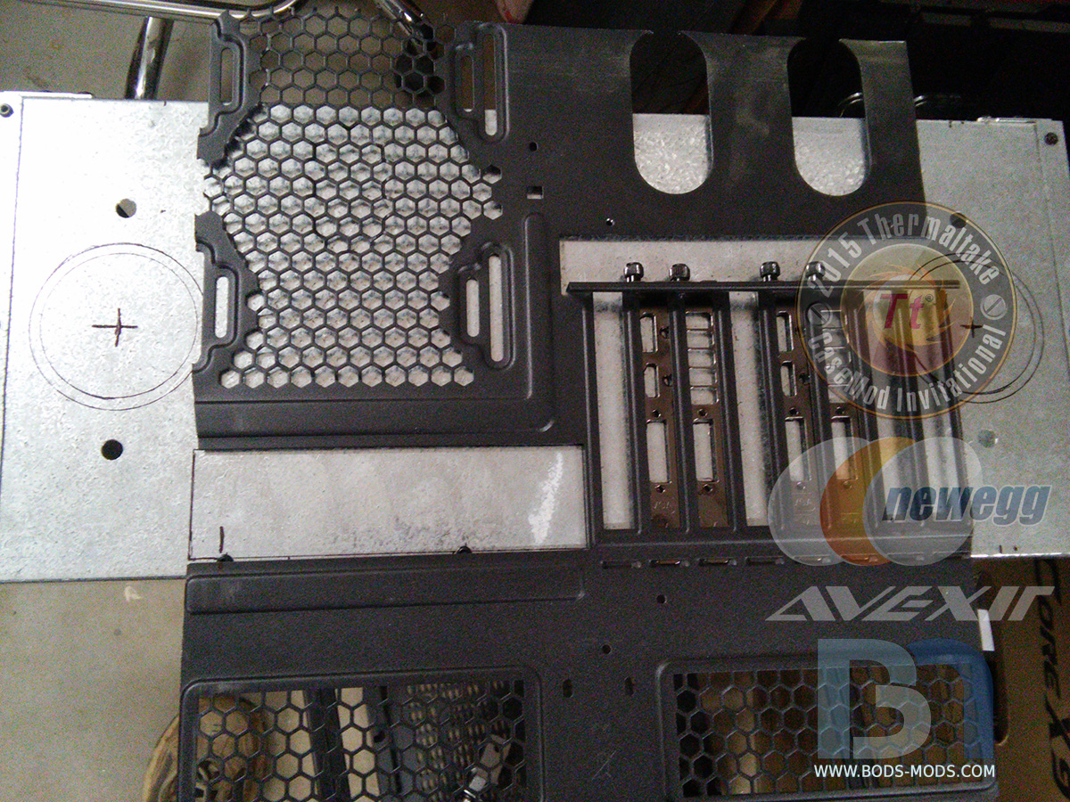
The time has come to create the opening for the motherboard's IO, but I needed the factory cutouts for a template. I couldn't just put the entire case up next to the inner chamber, so I cut it out.

Now I'm free to mark the openings with the stock "Ttemplate".. I included the GPU's IO brackets as well so I could transfer those holes for the displayport, HDMI, and DVI ports.

Holes marked..
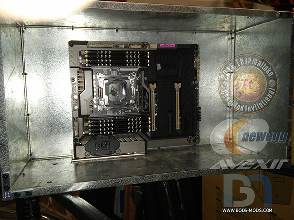
Motherboard IO cut and the panel in for a test fit..
With that in place I knew right where to add the standoffs, so now the motherboard is mounted.
Moving on to the GPU cutouts..
Graphics cards installed!
Next up is drilling holes for the pump wires, along with other cables such as USB3 and front IO.
-
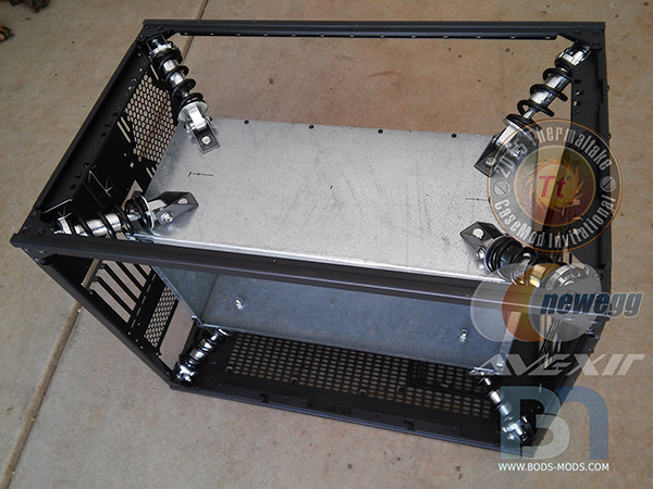
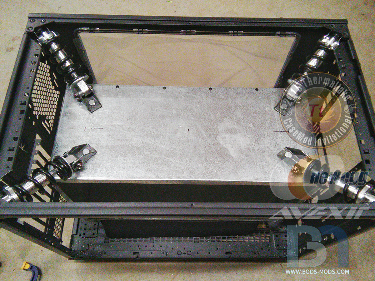
Got all the shock absorbers mounted over the weekend!
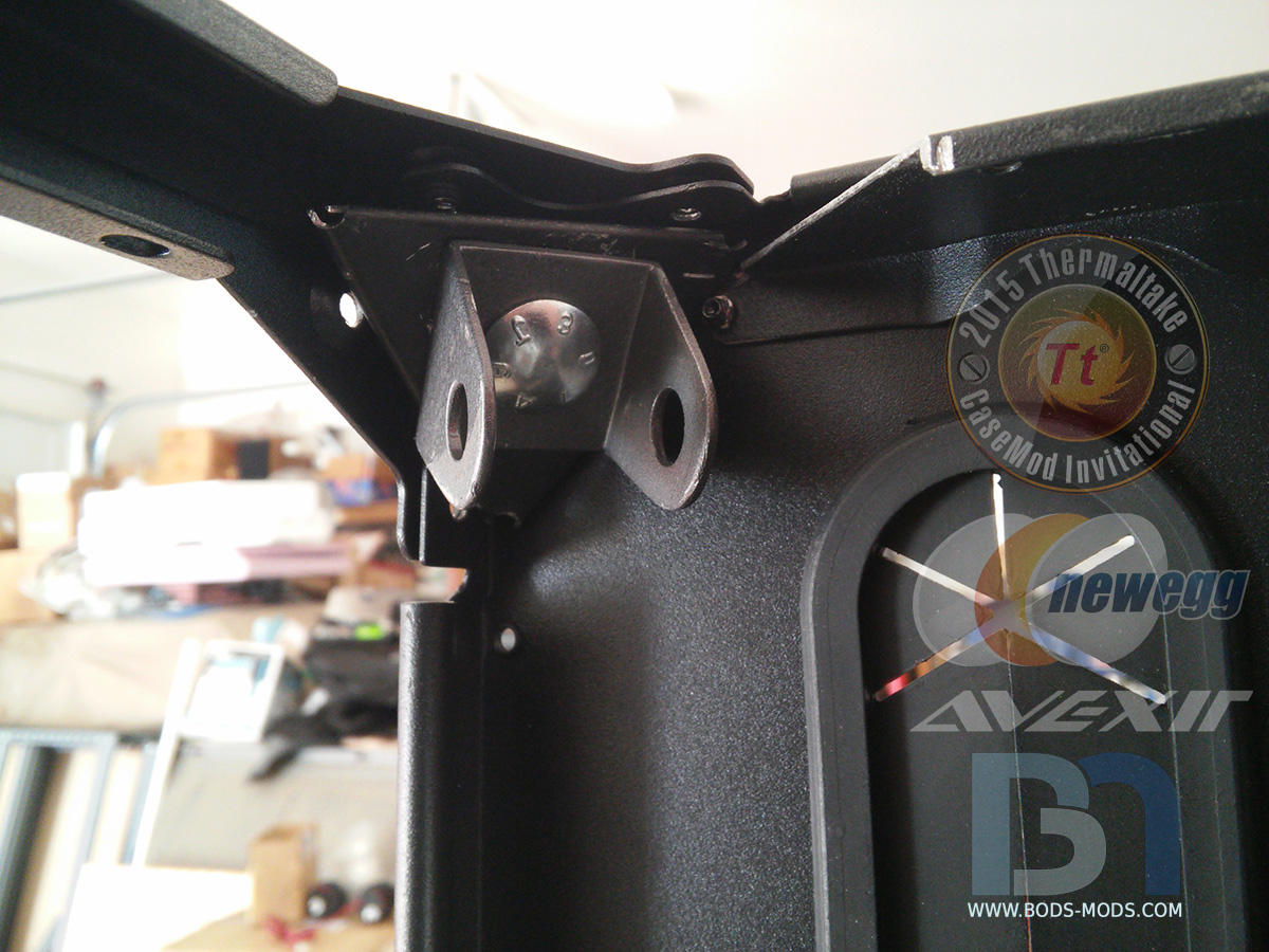
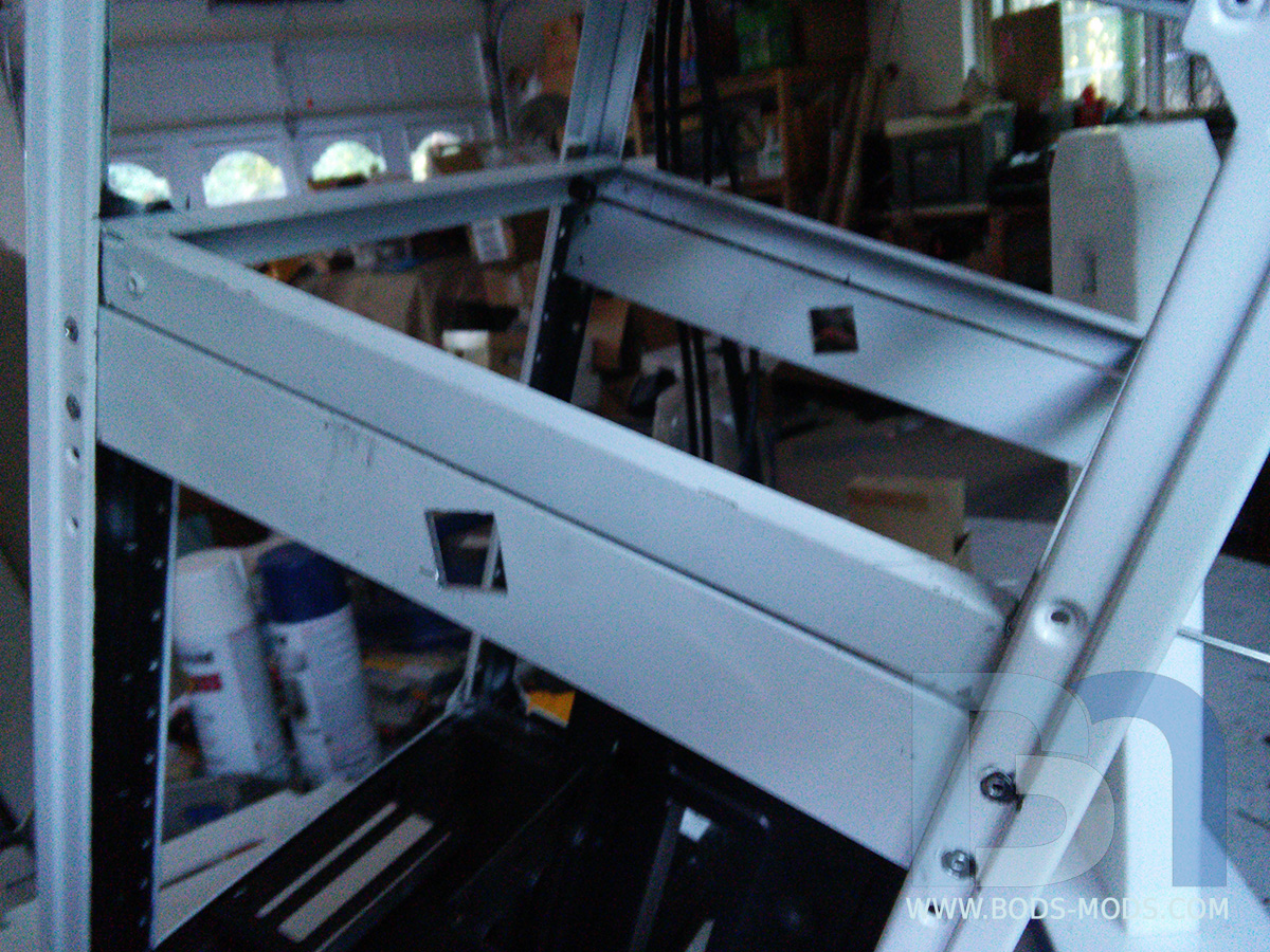
Working on the top shocks first, I got the corner shock brackets mounted into the corners using the existing pop rivet holes.
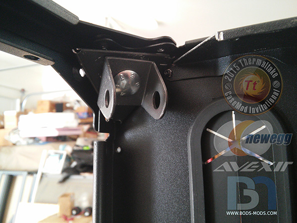
For the top shock mounts, I had to cut the ends off of the radiator support bracket to make room in the corners.

The back two shocks mounted..
..and the front two..
All four top shocks mounted to the corners.

After measuring and centering the inner chamber at the correct height, I drilled holes on all four corners to mount the other shock brackets.
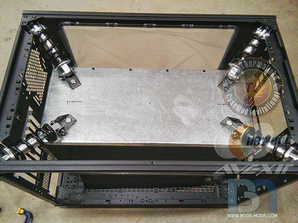
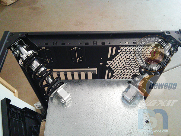
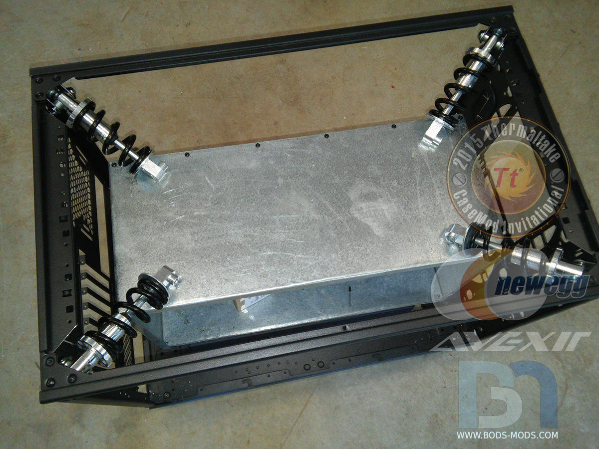
Flipping the entire case over, I started working on the bottom shocks.
I removed the inner chamber temporarily so I could have room to work, and proceeded to mount the remaining four shocks in the bottom corners.
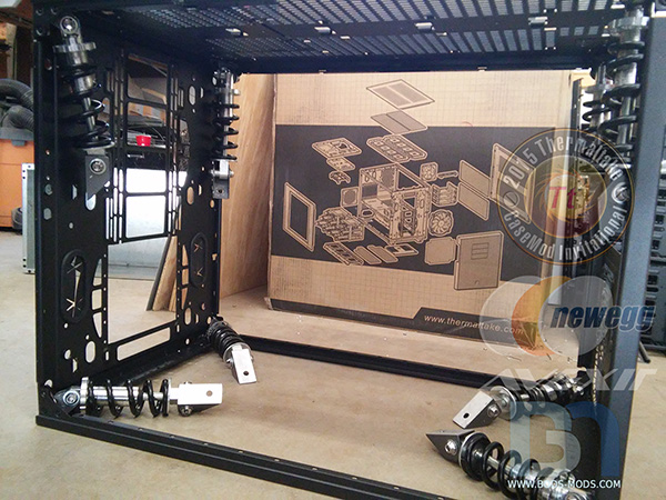
While the chamber was out, I drilled holes in the bottom using the same measurements as the top, and re-installed it into the case.
We now have a fully suspended inner chamber!
- Richi, hotcoolman and AlShuryan
-
3
-
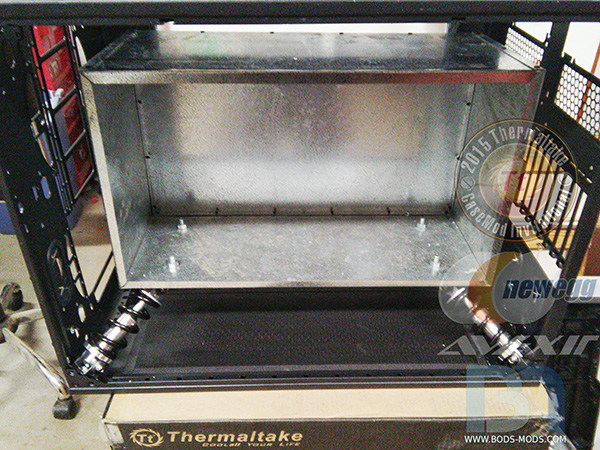
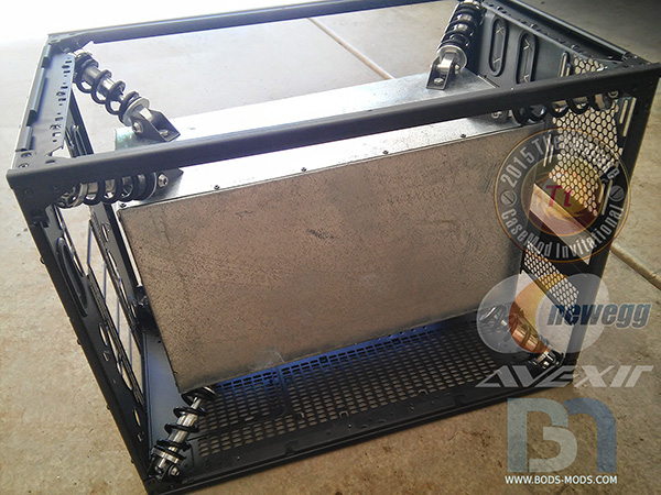
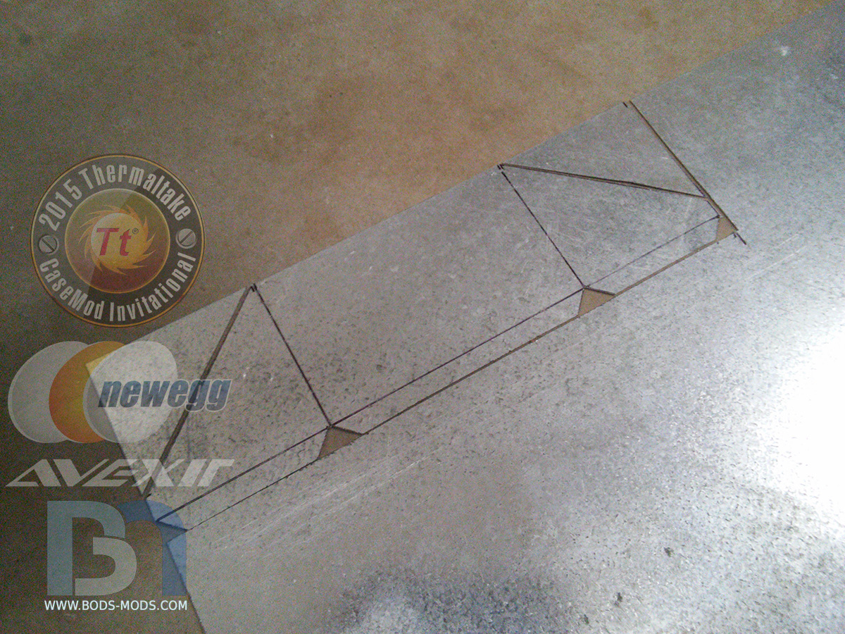
The inner chamber of the Adrenaline Transport Container was completed over the weekend, using only the highest grade galvanized steel sheet. The galvanization process alters the molecular structure of the steel, creating a superior adrenaline-proof barrier, should any leaks occur. Our courier's safety is of utmost importance here at Adrenaline Express!
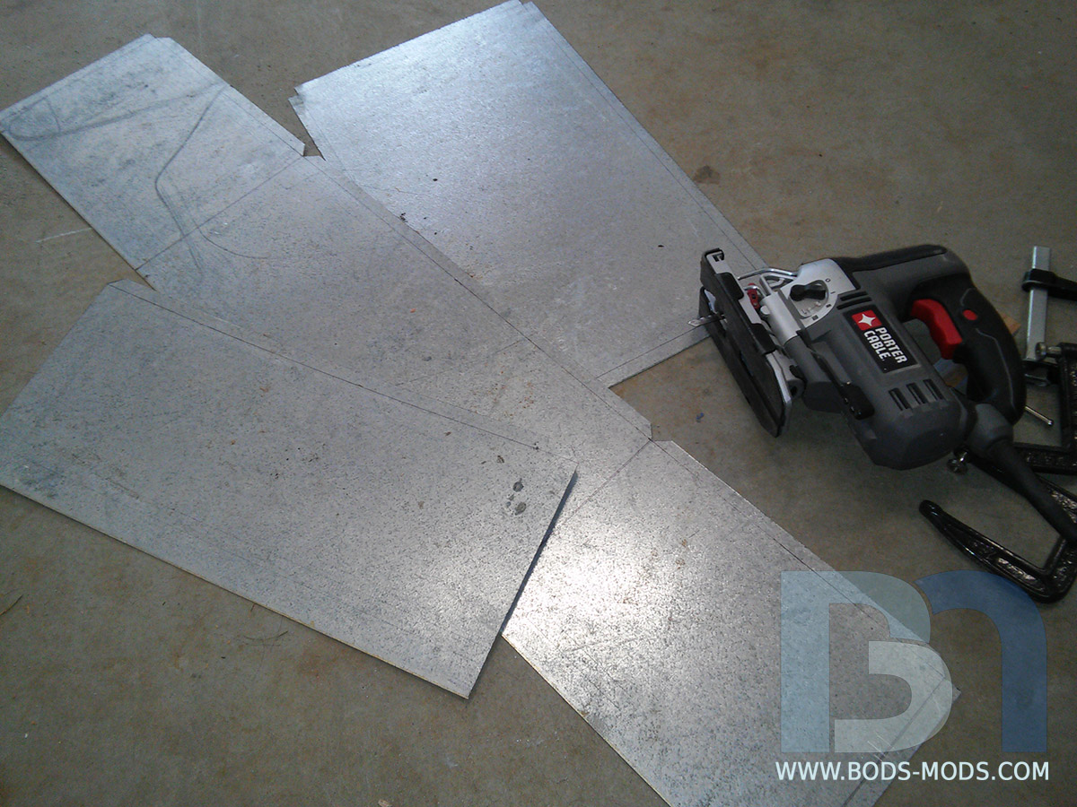
Marking out the dimensions of the inner chamber onto raw galvanized stock.
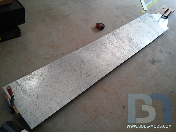
A jigsaw outfitted with high tensile strength tungsten carbide blades was used to cut the specially treated steel.

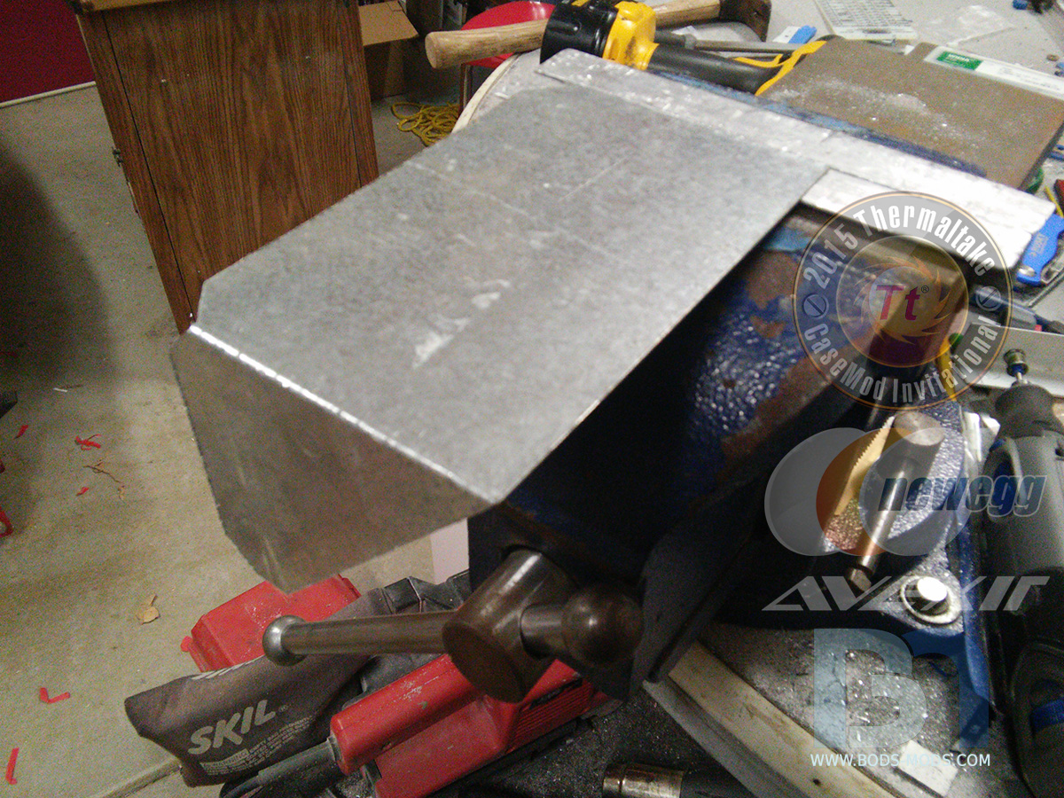
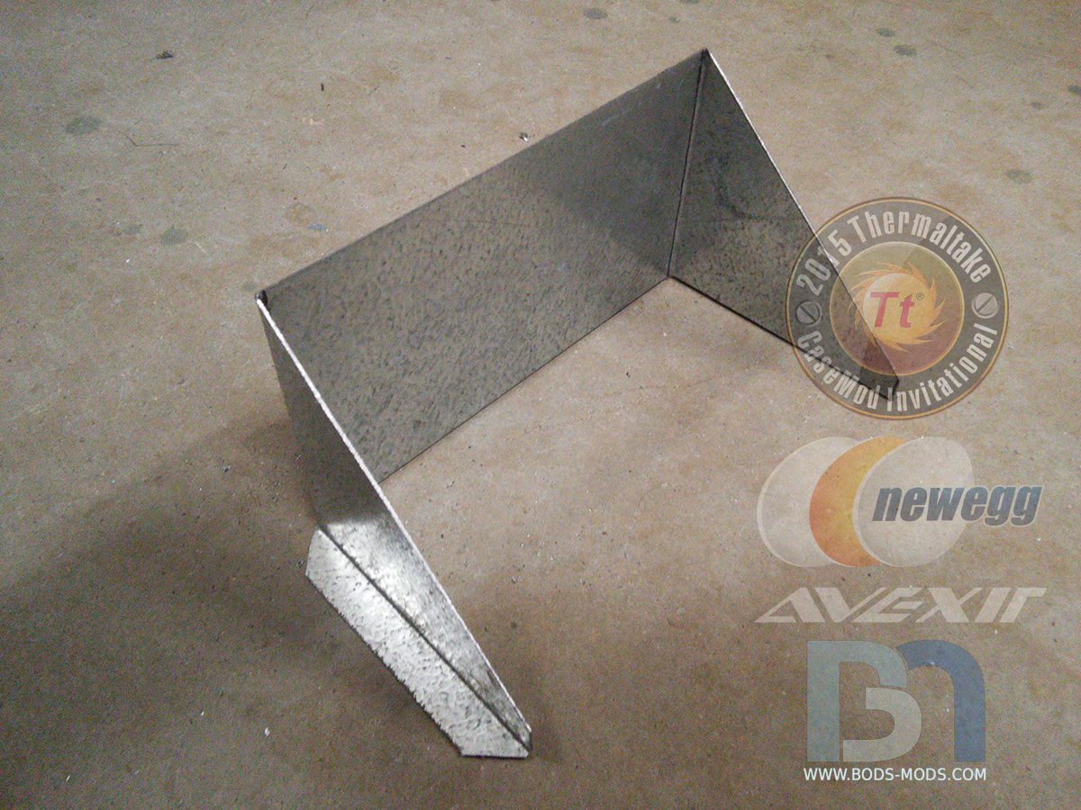
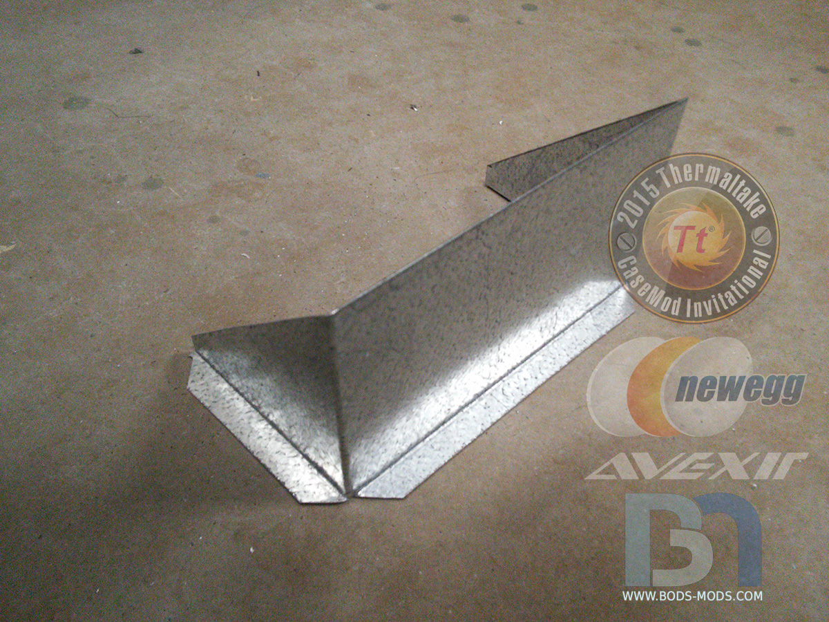
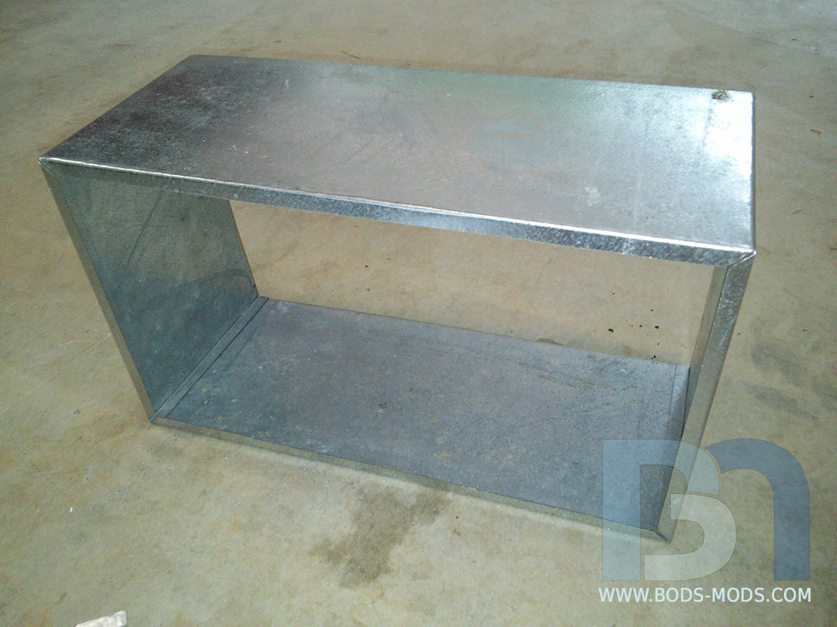
After bending, we have four sides.

A separate piece for the back was made, with a 1/2" lip all around..
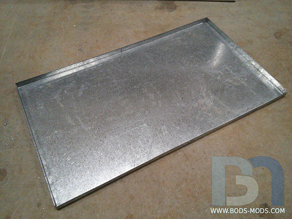
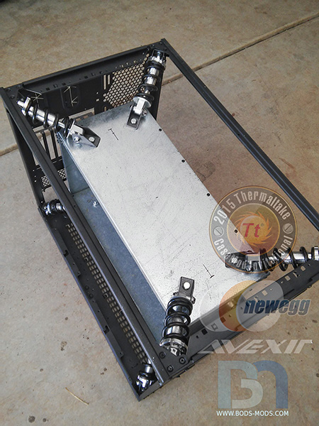
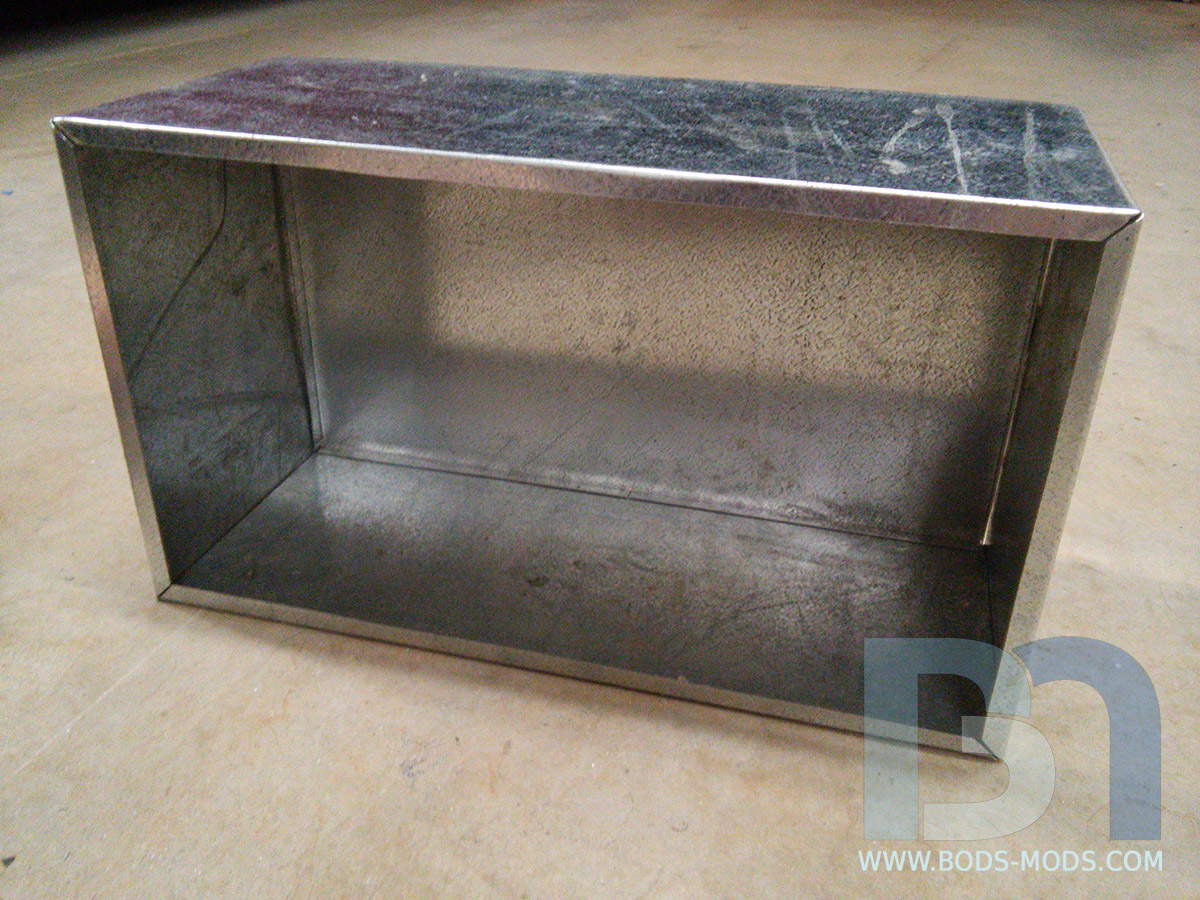
The back fits perfectly inside the four sides.
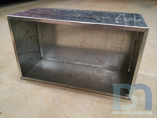
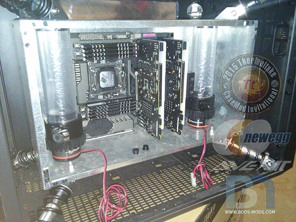
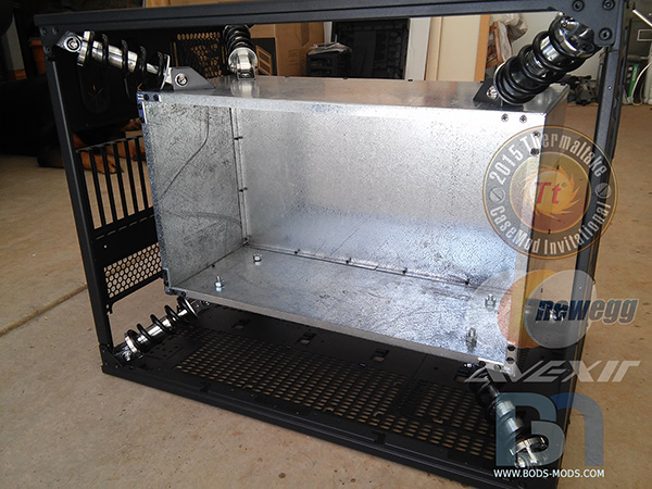
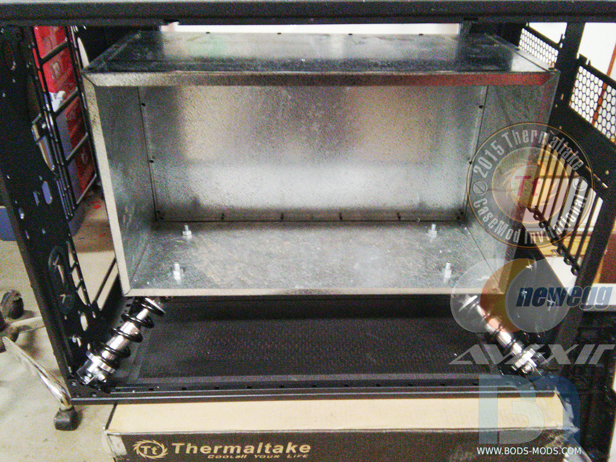
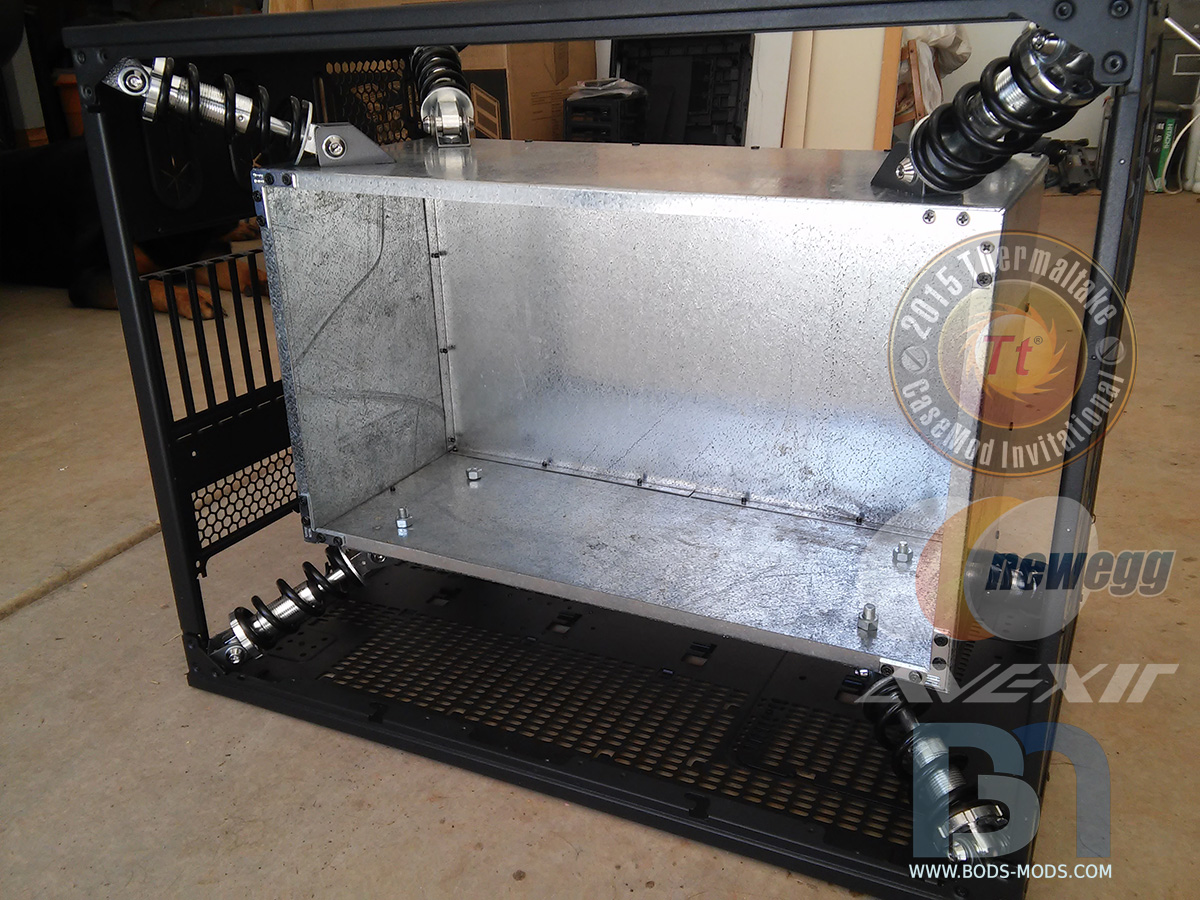
Once riveted together, I could start test-fitting parts inside the chamber. First was to ensure the two Adrenaline Reservoirs would fit snugly in their places.
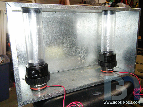
Next will be placement of the main control board, which will be responsible for regulating the environmental conditions of the chamber, as well as monitoring vibrations.
-
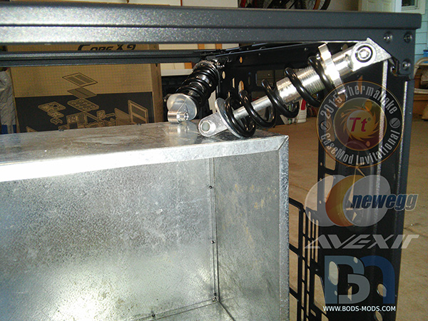
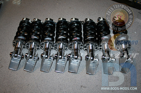
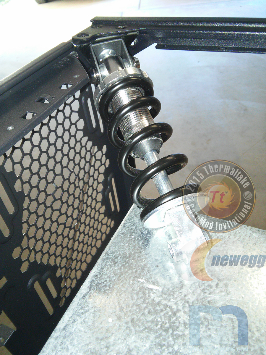
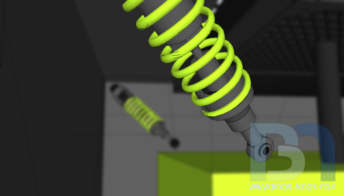
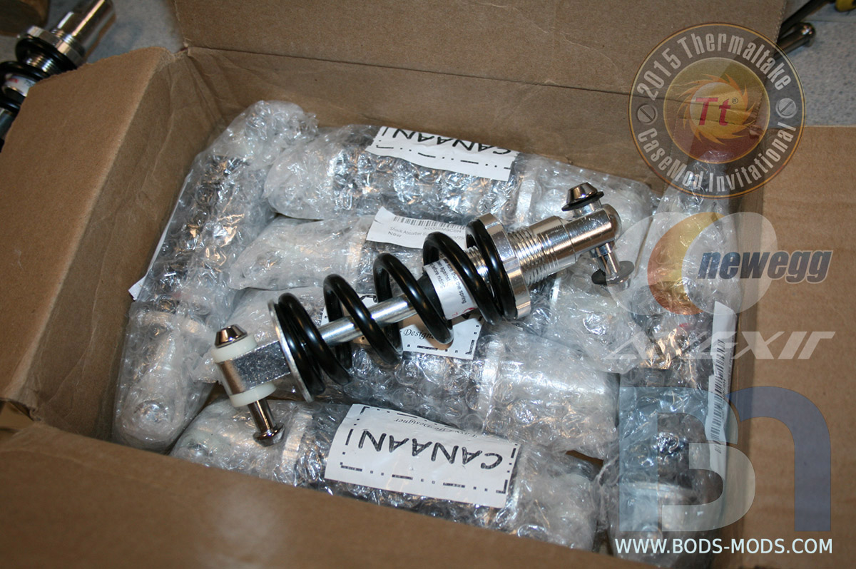
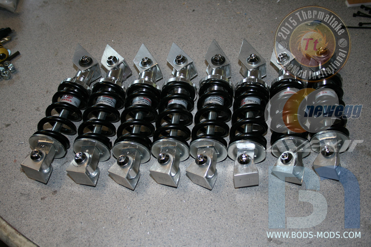
Since Adrenaline is such a potent chemical, it must be handled very carefully. If just one drop should escape from its container, the consequences would be devastating. So first and foremost, construction of the transportation unit is critical, and extreme care in keeping the Adrenaline stable is paramount. That is why these heavy duty shock absorbers will be employed on every corner to ensure that no vibration makes its way into the container..
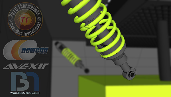
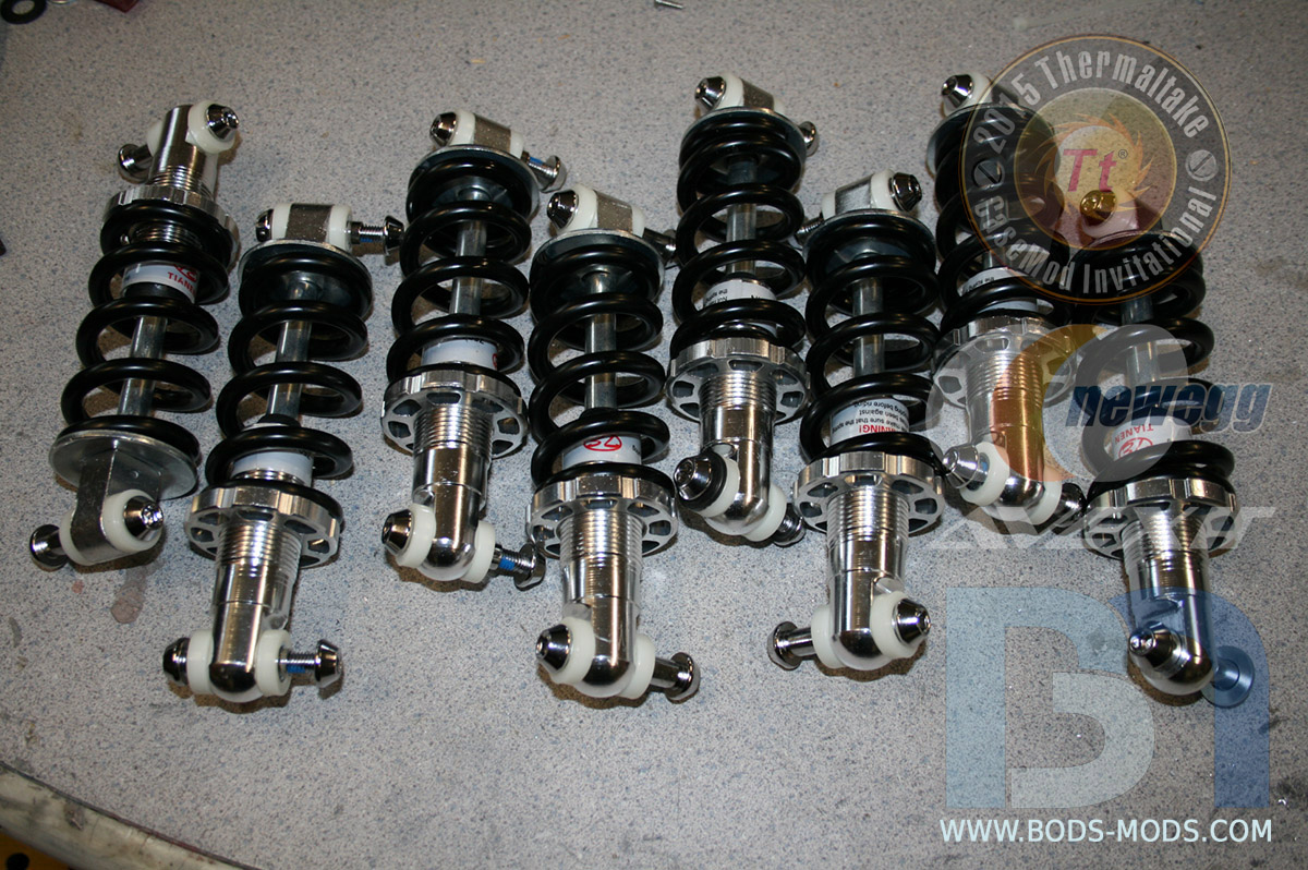
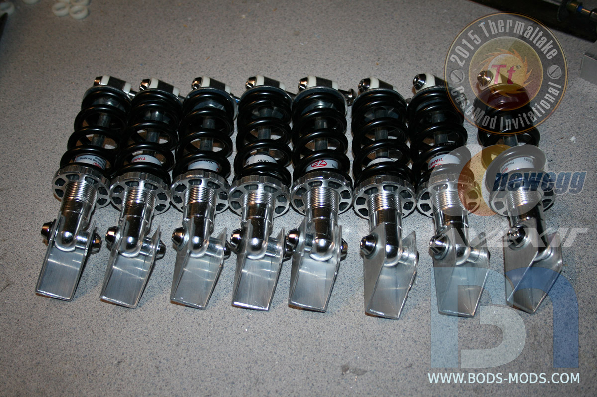
These heavy duty shock absorbers, normally used on full suspension mountain bikes, will be put to better use here.

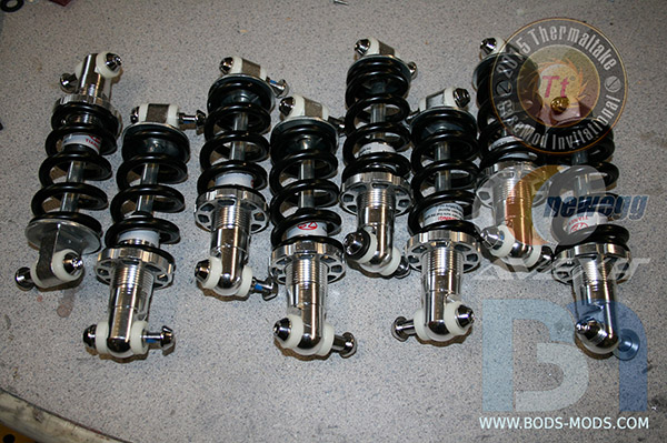
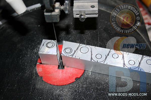
Taking 1" square box tubing, I cut eight individual pieces out for mounting the shocks to the inner chamber.
The shock fits inside the bracket, utilizing the mounting hardware that came with it.
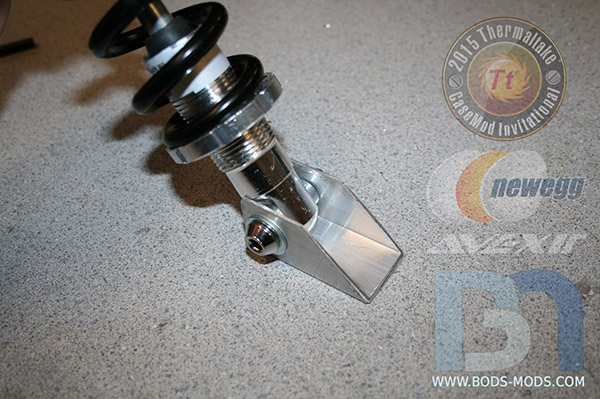
All eight chamber mounts done.
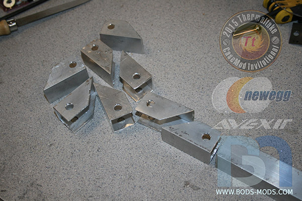
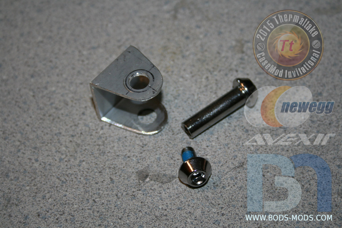
For the other end, a slightly different design was needed to mount the shock to the corners of the outer frame. More 1" box tubing was sectioned out.
Cut and drilled to accept the shock bolt.
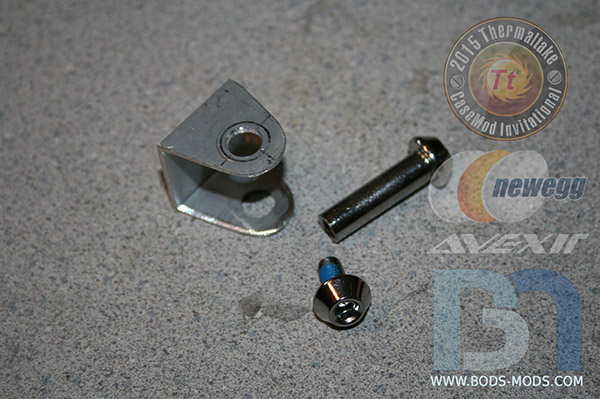
All mounting brackets done!

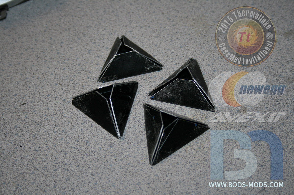
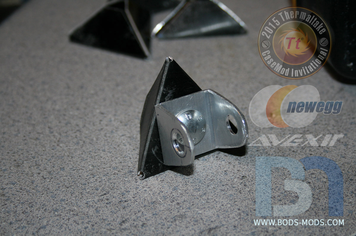
These triangle pieces will fit into the corners of the frame.
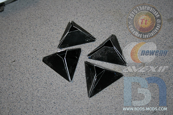
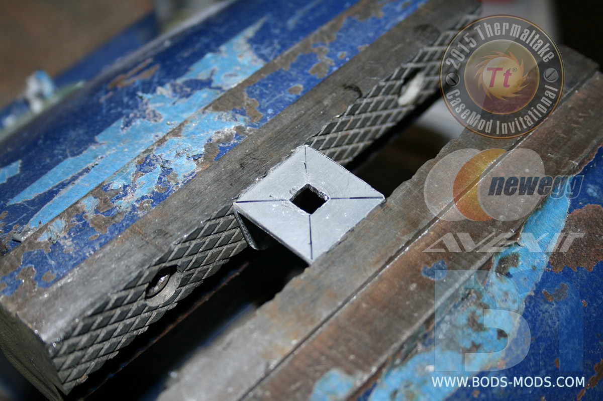
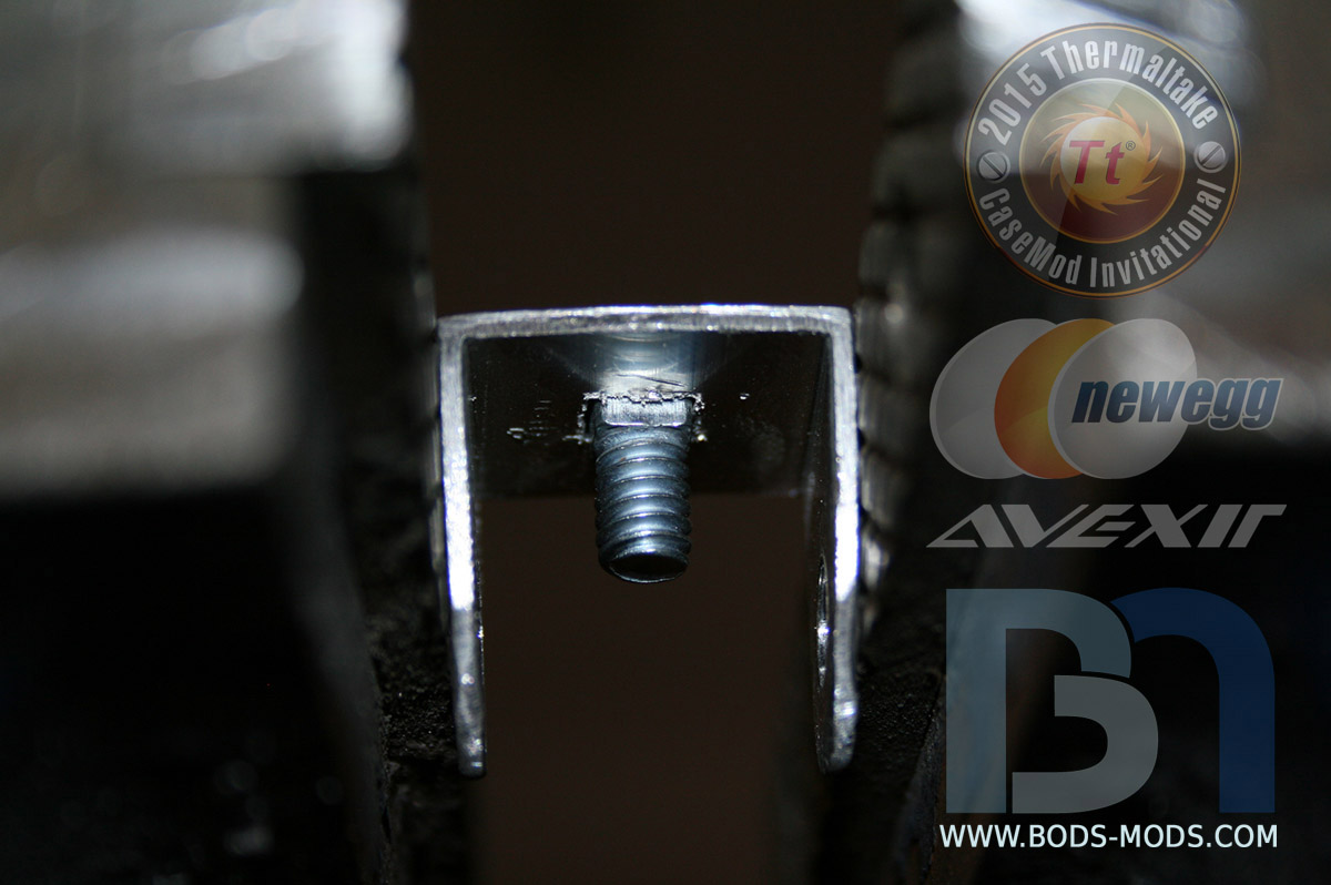
The top brackets are drilled in the center, and the holes squared.

This keeps the carriage bolt from spinning when the nut is screwed on.

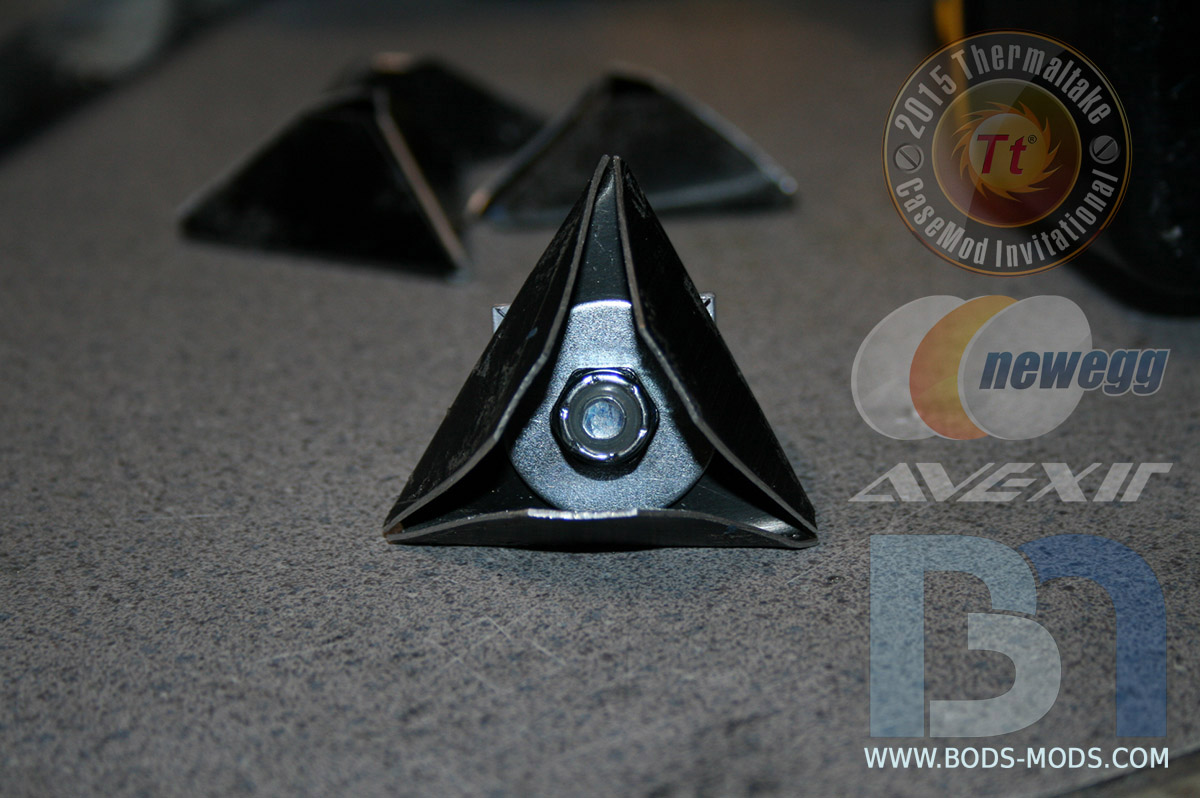
Both pieces fastened together.
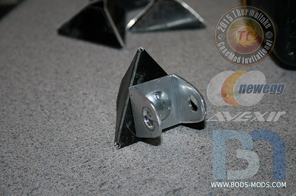
A 1" flat washer is used to reinforce the bracket and spread out the load.
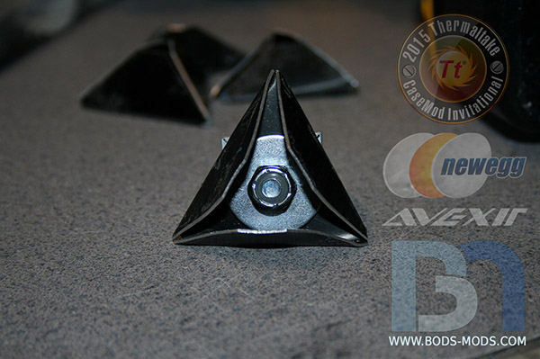
Once the frame is prepped, these brackets will then be riveted into place. More soon!
- hotcoolman, ToniMaroni77 and AlShuryan
-
3
-
I really like the X9, not only for it's size, but also for the shear number of options and configurations one can choose to go with when building a system. It literally takes the boredom out of putting a computer system together because it can be built in so many different ways within this one chassis. This is evidenced by the myriad of X9 rigs out there right now that people have built for themselves and others, each one vastly different than the next, much like snowflakes in their uniqueness.
That's why when I took delivery of my X9, I felt a sense of anticipation, as if I was stepping into the unknown, my path uncertain. I was giddy with excitement, eager to tear into the box like a child and his present on Christmas morning. My heart started racing and I quickly scribbled my illegible signature on the delivery man's tablet and waved him off, never once taking my eyes off the box. My new enemy became the very cardboard that had served to protect that which was concealed inside, and was quickly subdued as I targeted its weakest points with the first thing I could find within reach: my house key. Stabbing the packing tape repeatedly along its seams, I eventually succeeded in opening the box, only to find the X9 was yet unseen; obfuscated by Styrofoam and plastic (Dr. Cardboard's obvious cohorts). But even these final layers of protection were no match, and ultimately yielded to my unrelenting desire to gaze upon my new case.
After a few moments of silent staring and admiration, I took a deep breath as I began to contemplate my seemingly impossible task of deciding what to do for a theme. The choices are virtually unlimited! How can I settle on one single idea? Should I go with a video game theme, or movie? What could I do that hasn't already been done a hundred times over? Then the answer just appeared before me as I watched the delivery truck start up outside and drive off. This whole thing that I had just experienced, the anticipation, the excitement, the excelerated heartbeat... it was like getting a shot of adrenaline. Before the X9 arrived, I was bored, tired and lethargic. And once it got here, I felt awake, motivated, inspired.. I felt alive! So this theme will exemplify that feeling of heightened alertness. The Core X9 will become the vessel that transports this highly exuberant chemical to its new owners, curing them of the common doldrums. Of course, there is only one company internationally certified to carry such a fragile, and extremely rare commodity...
And that company is:
- AlShuryan and Tt Shannon
-
2
-
Greetings everyone! It's such an honor to be selected to represent the US in Thermaltake's CaseMod Invitational, Season 2! This is going to be a really exciting competition, with so many talented modders battling it out. I can't wait to see what everyone comes up with, using the X9 chassis.
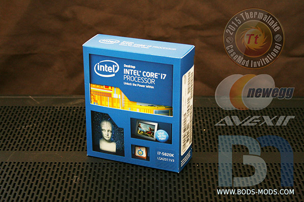
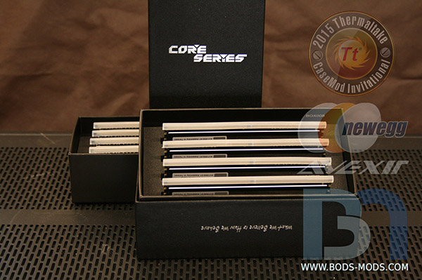
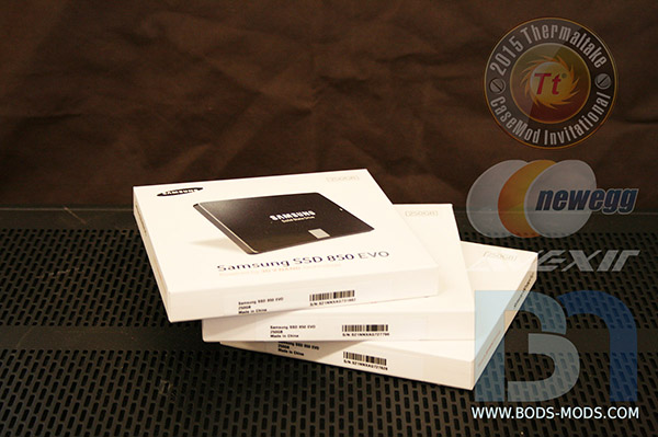
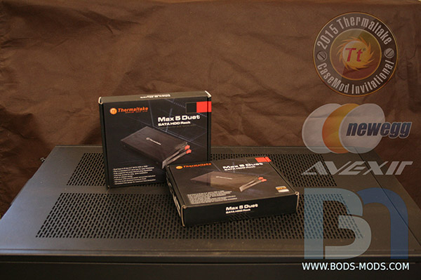
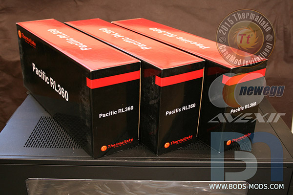
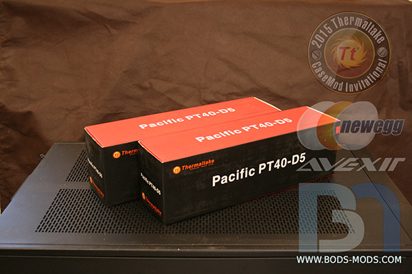
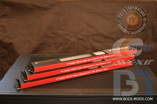
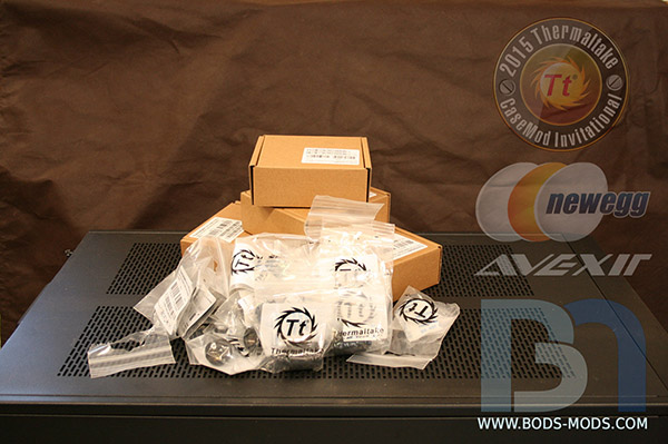
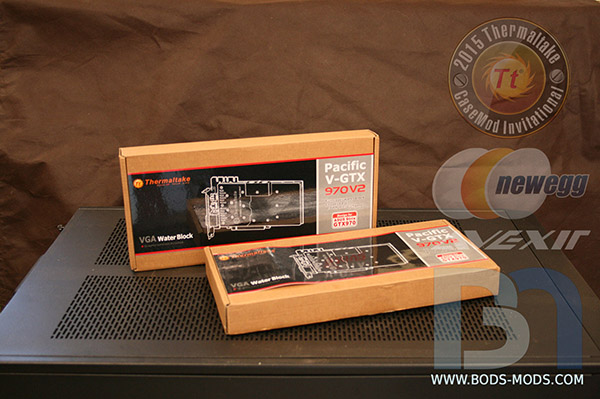
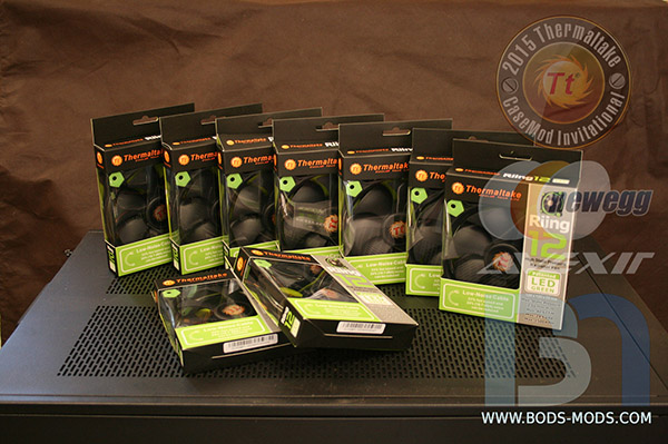
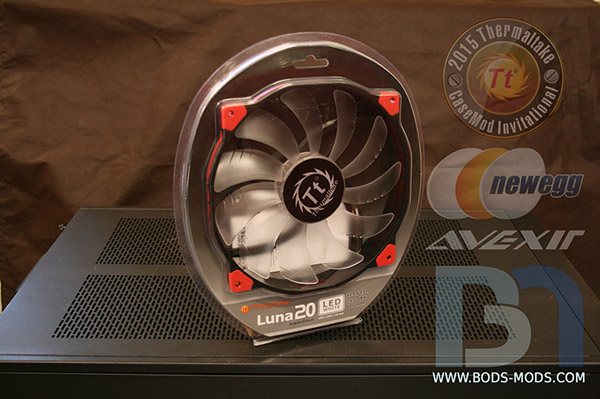
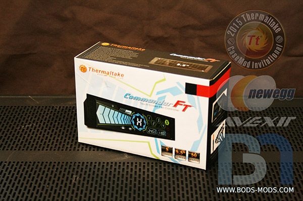
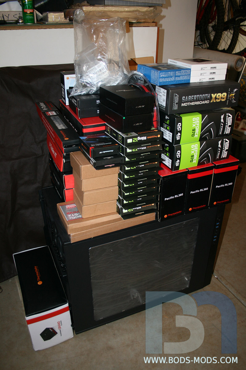
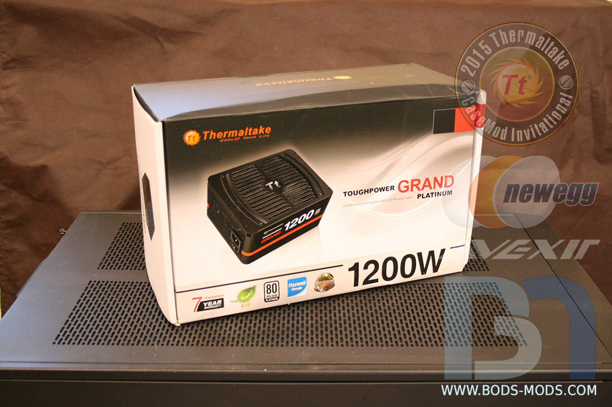
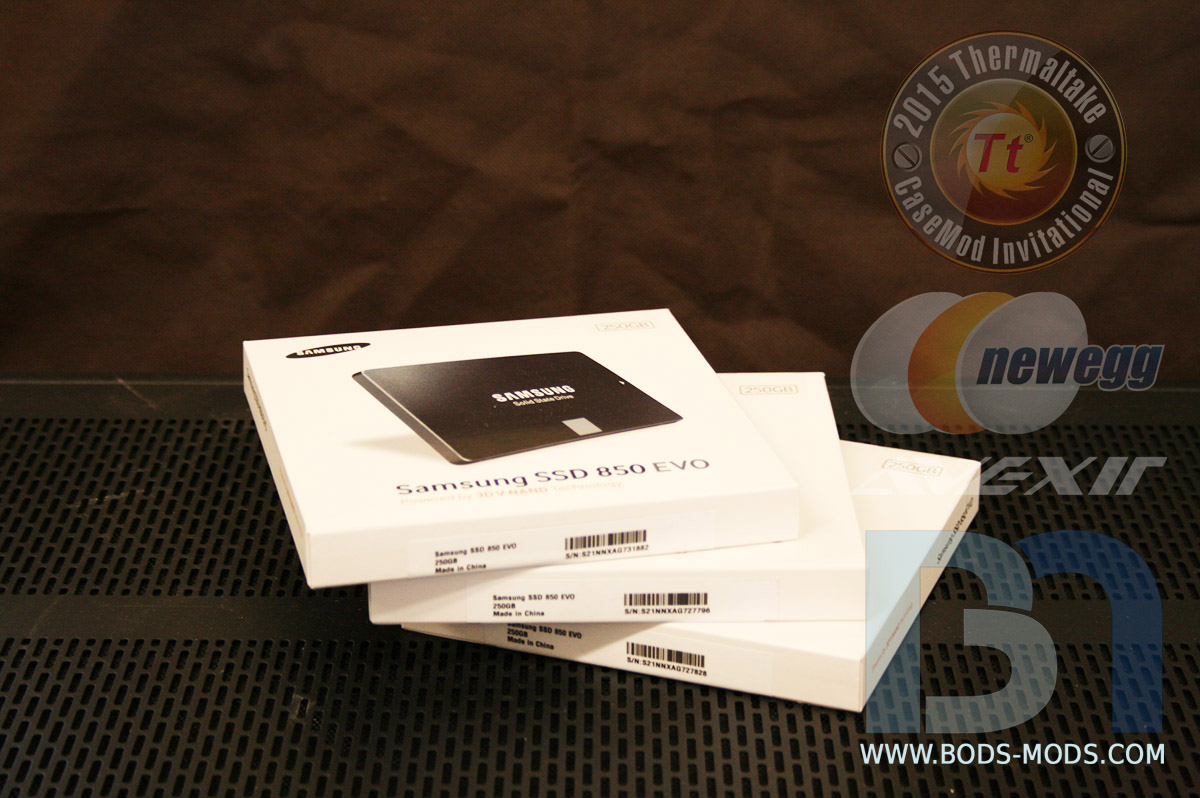
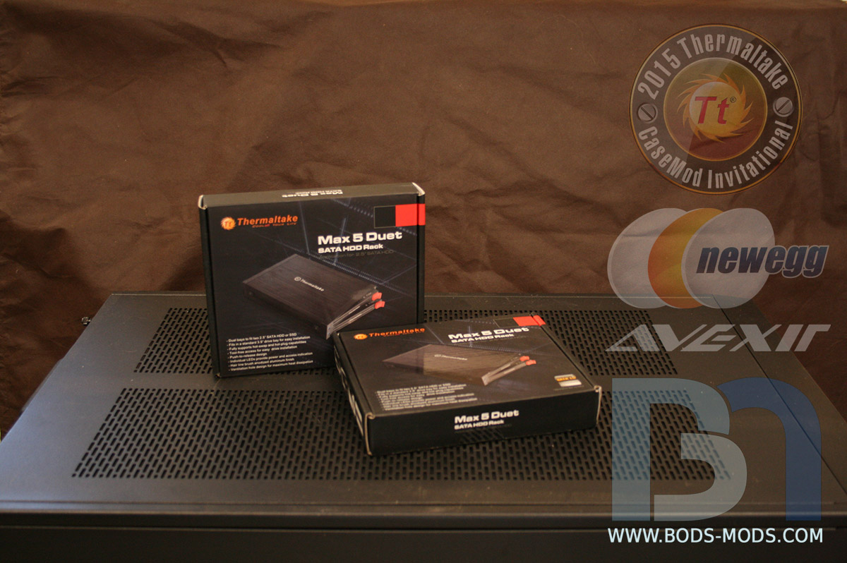
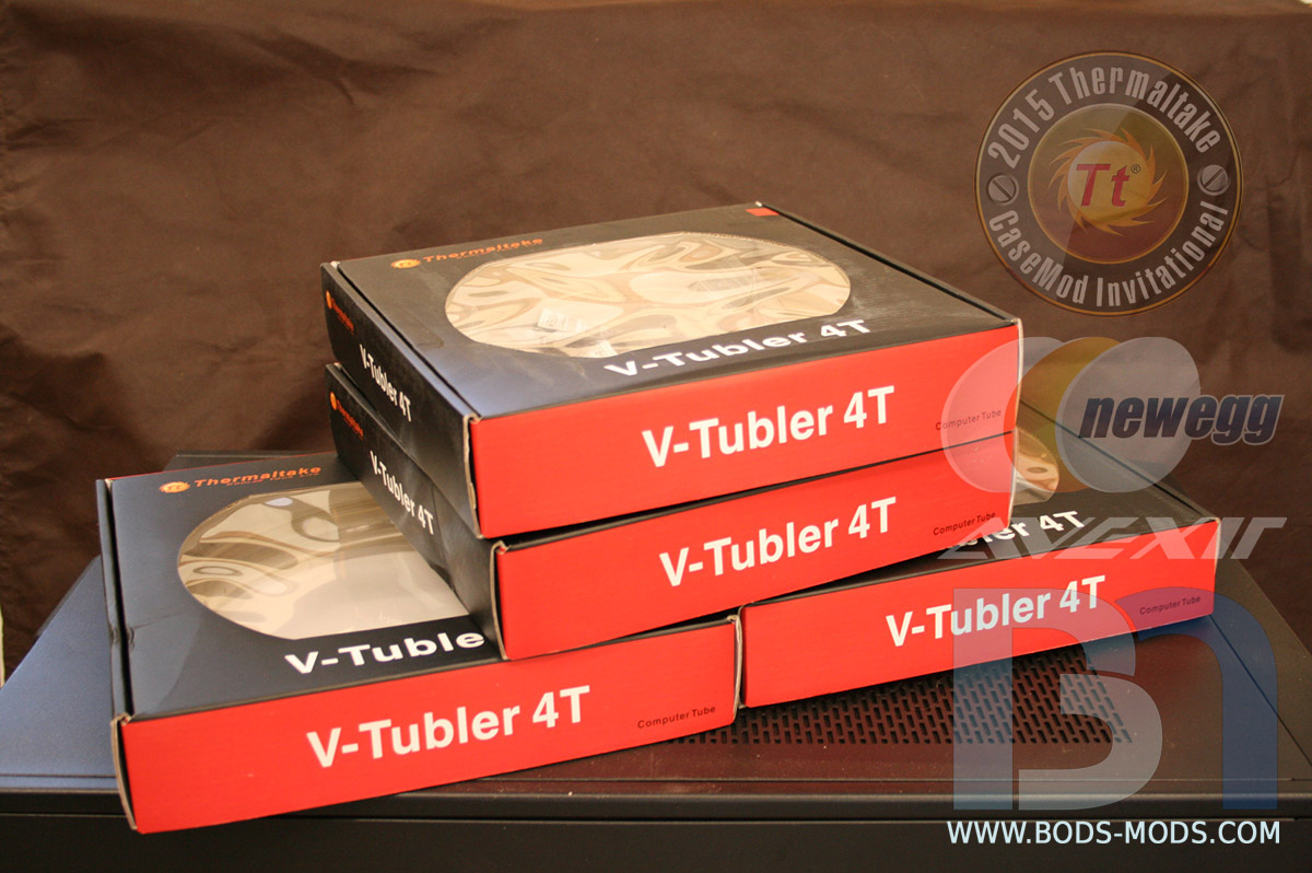
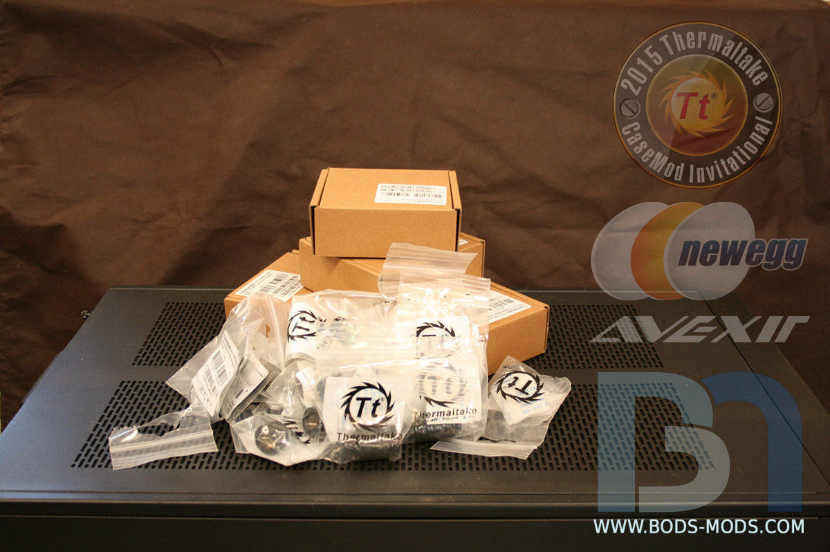
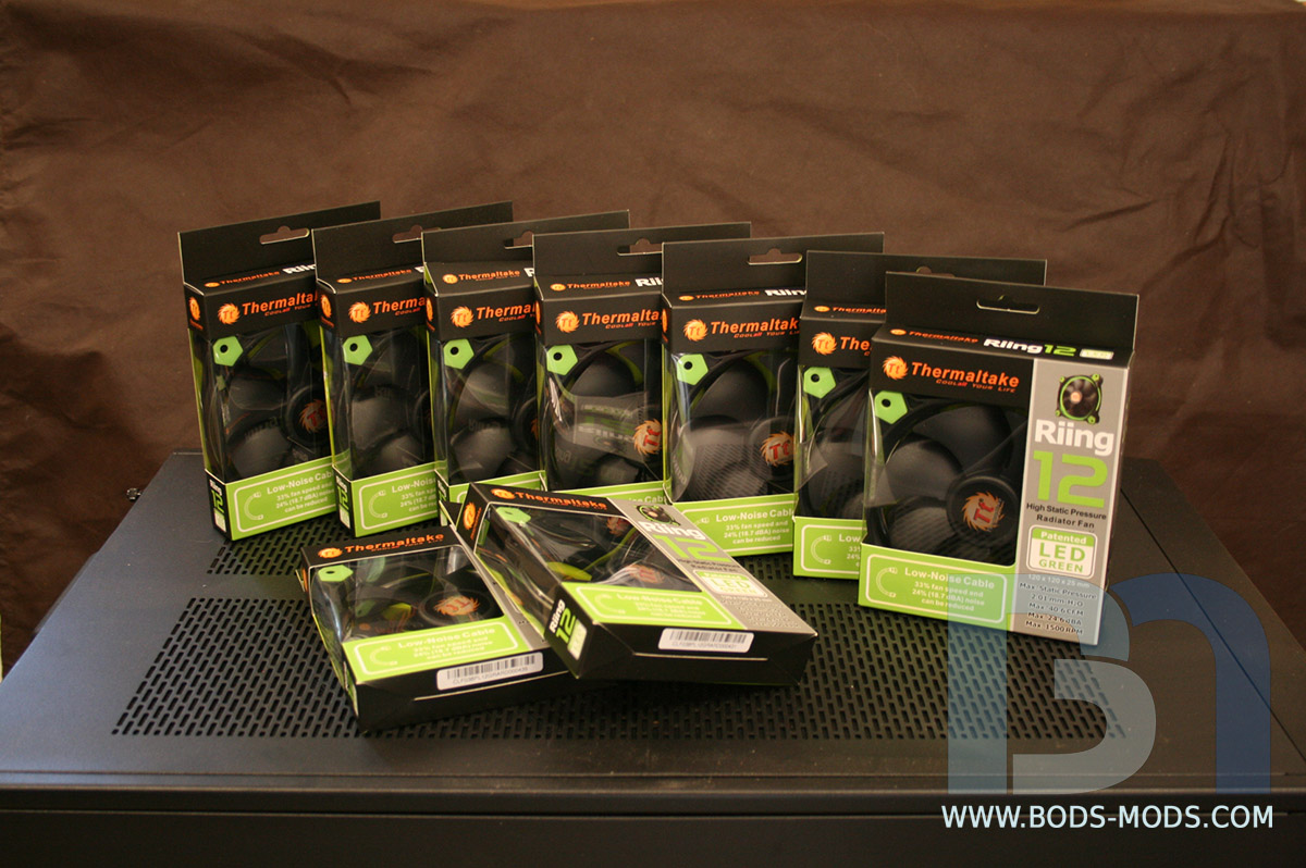
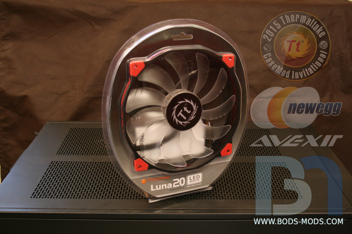
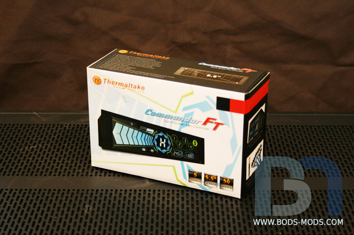
Here are my requisite photos of all the great hardware that will be going into this build. Special thanks go to not only Thermaltake for hosting this amazing competition and providing for most of the hardware, but also to Avexir for the sweet DDR4 memory kit, and to Newegg!
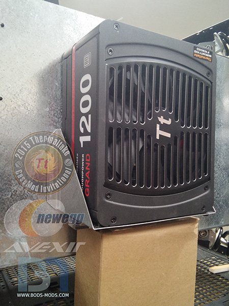
Here is an overall shot of the booty, case and all..
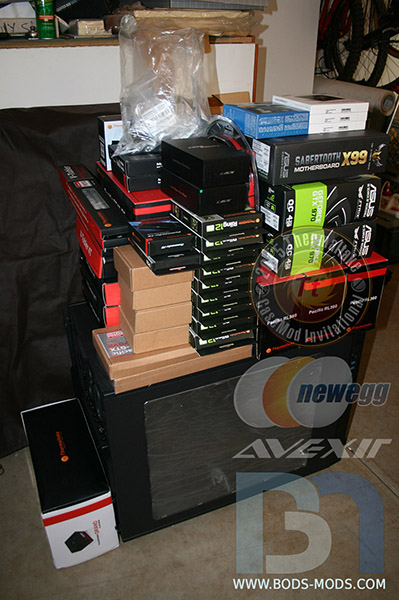
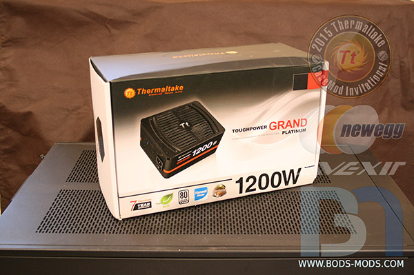
Thermaltake ToughPower 1200w power supply
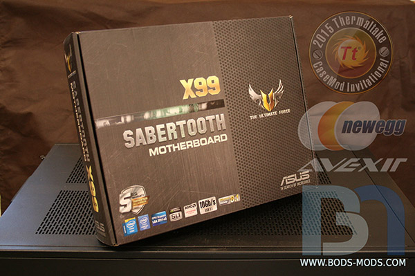
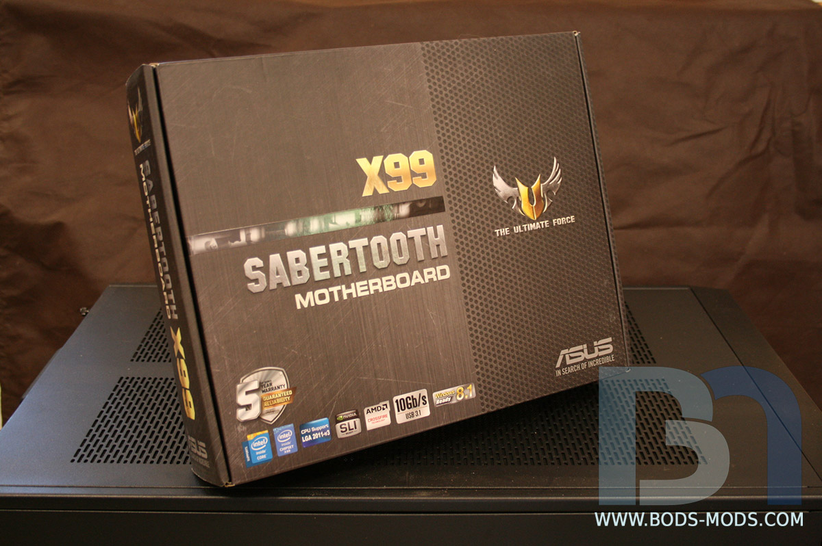
ASUS Sabertooth X99 motherboard
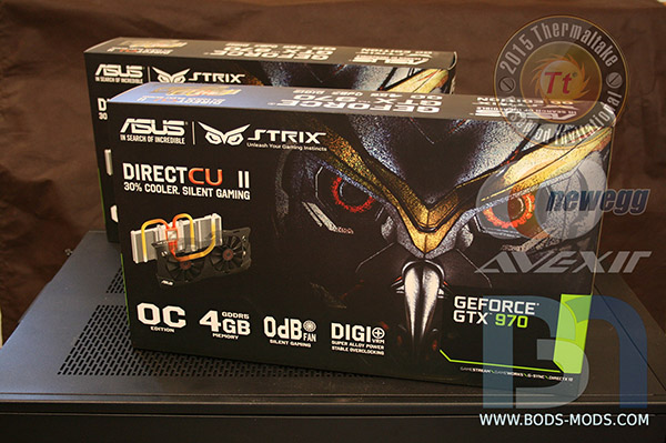
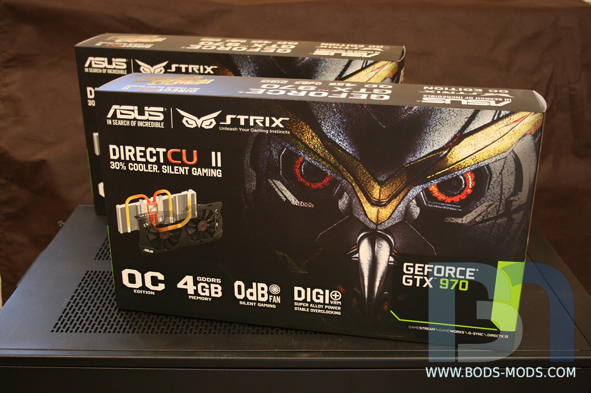
ASUS Strix GTX 970 video cards X2
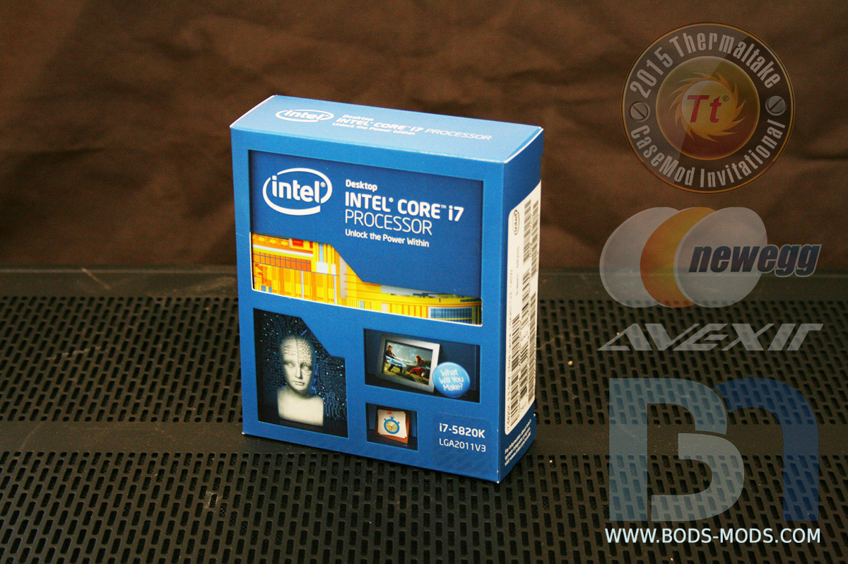
Intel i7 5820K processor
Avexir DDR4 16Gb Memory Kits X2
Samsung 850 EVO 240Gb SSDs X3
Thermaltake hot swap dual drive bays X2
360mm Rads X3
200mm Res/Pump combos X2
Soft tubing

Rigid tubing
Miscellaneous fittings (too many to itemize lol)
STRIX 970 waterblocks X2
120mm Riing Fans Green X9
200mm Luna Fan white
Commander FT Fan Controller
Commander FX 10 port Fan Hub
- Tt Shannon and AlShuryan
-
2
-
I decided to add a third hard drive, a 5/14" platter drive to use as backup/storage. So I added another connector to the sleeved cable, and flamed the frayed parts a little. Looks a bit better now.
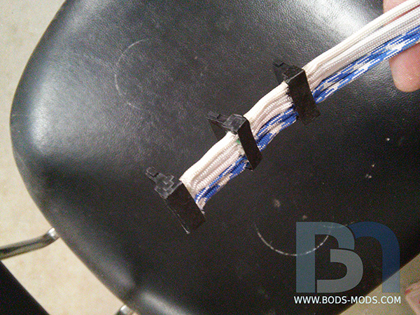
And because the 5 1/4" drive was bigger, I had to make a couple adapter plates for the SSD's so they would be at the same level. Now the cable can go straight across all drives.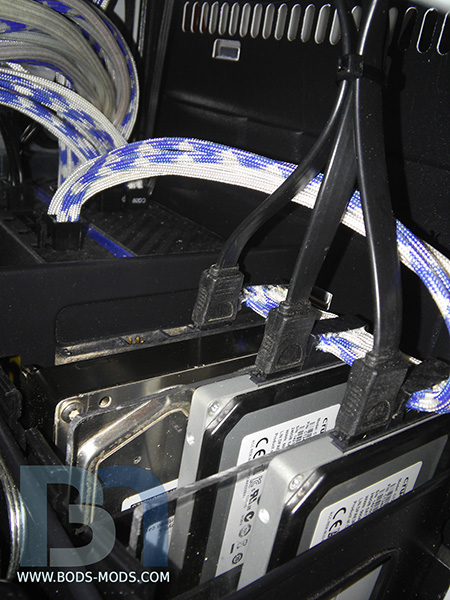
With the drives done, I moved on to installing the Titan one final time. I couldn't help myself, and had to give it some extra paneling for added detail.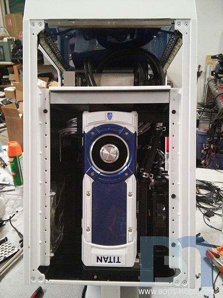
Buttoning up the case, putting all the panels on, and finally the legs.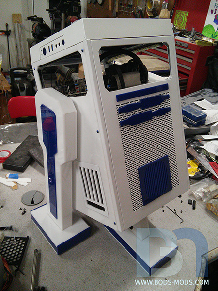
System up and running on my son's desk!
Of course, it all can't go so smoothly. Upon starting it up, I got the ol' "Missing operating system" error message. I'm hoping I can fix the MBR and it will be fine. Otherwise I'll have to reinstall the OS. -
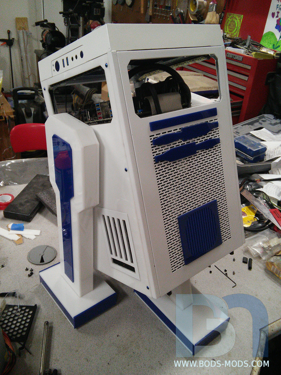
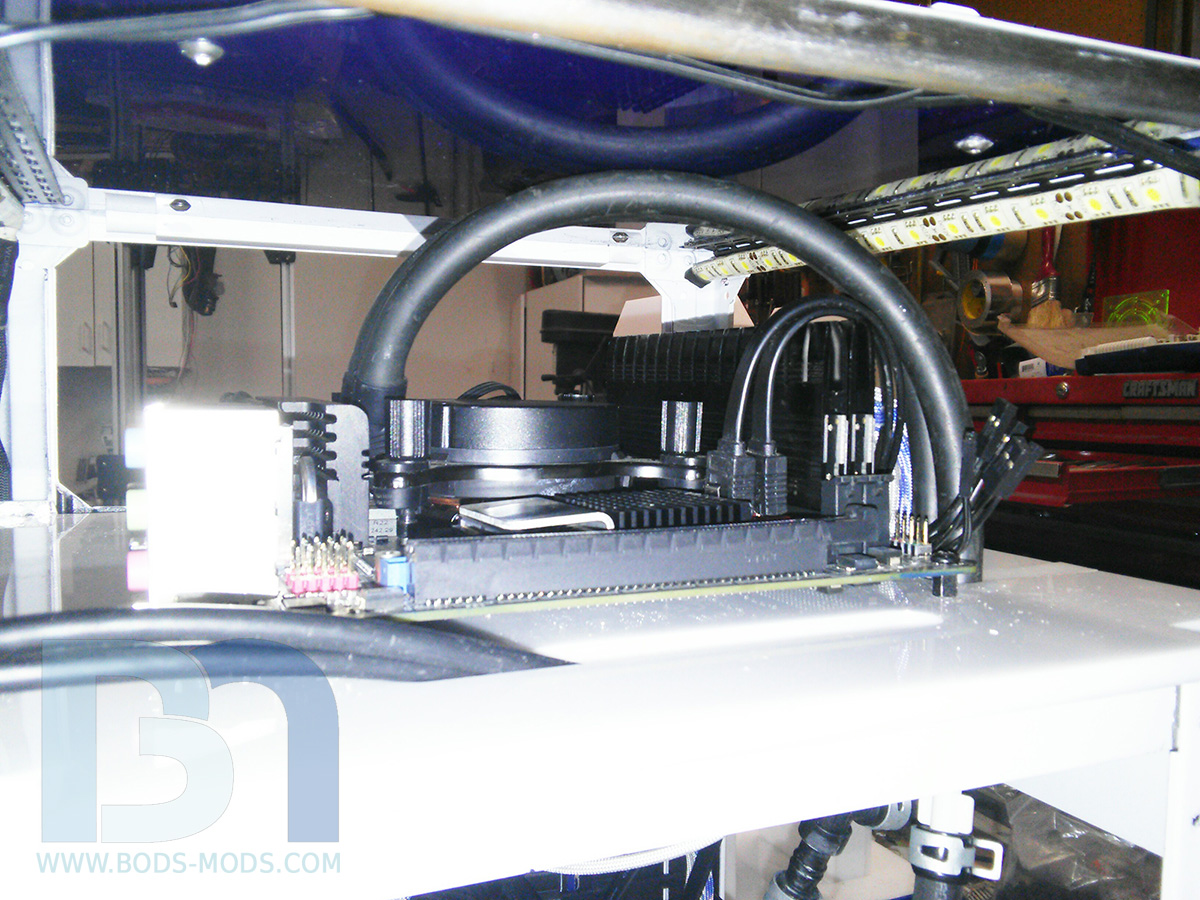
Started assembling the system the other day, which required confiscating my son's rig to get the parts out of it. Upon fitting the Tt AIO cooler into R2, I realized it was too short to reach the motherboard where I had intended to mount the rad. So after a few conniption fits and weighing my options, I decided the best route would be to extend the hoses of the AIO. Since I had never done this, I wasn't sure it would work properly once I opened up the factory-sealed closed loop system. But after more research and some consultation with Shannon, I went for it. And it actually ended up being a really simple process!
I went to a local auto store and picked up some rubber hose, 1/4" barb elbows and unions, and a universal T fitting (they didnt have a 1/4" T). I cut the stock hose about an inch from the rad and inserted the 90º elbows. Then added two 4" pieces of new hose followed by a union barb on one line and the T fitting on the other. Once everything was connected and clamped (didn't really need the clamps), I situated the cooler so that the T was the highest point in the loop and refilled the unit. I cycled the pump a few times and topped off until all the air was out, and done!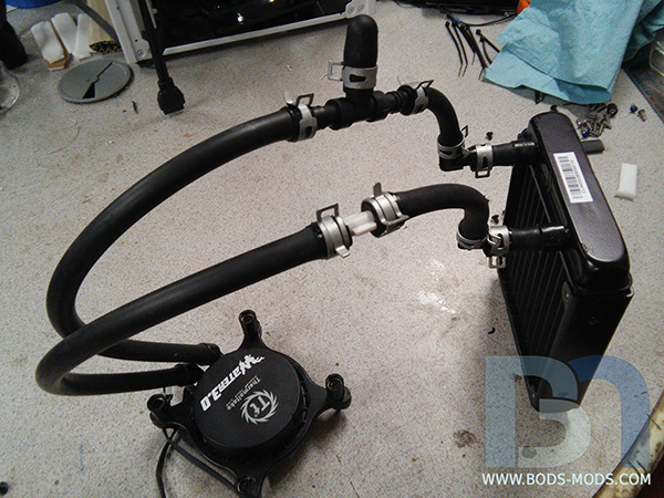
Here's a couple shots of the cooler installed in the case.

And a couple of the overall assembly..
Tonight I will get the video card installed, the panels on, and finally the legs. Then I can call this one done!
-
I'm almost done with this project, but I have to get caught up on my pic posting. I finished sleeving the PSU over a week ago, and have been taking care of various, unexciting little things like the small white trim pieces for the posts, and other 120mm fan mounts.
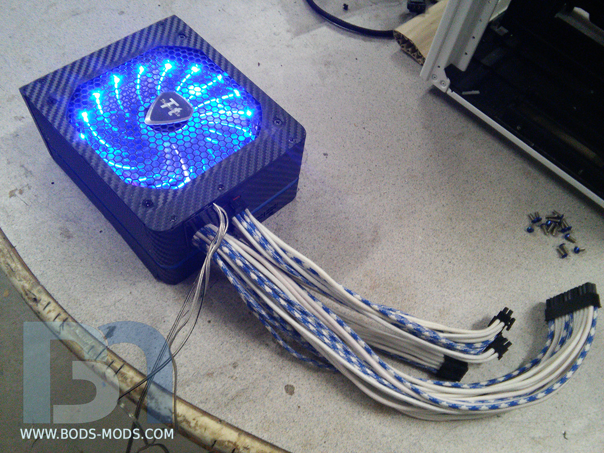
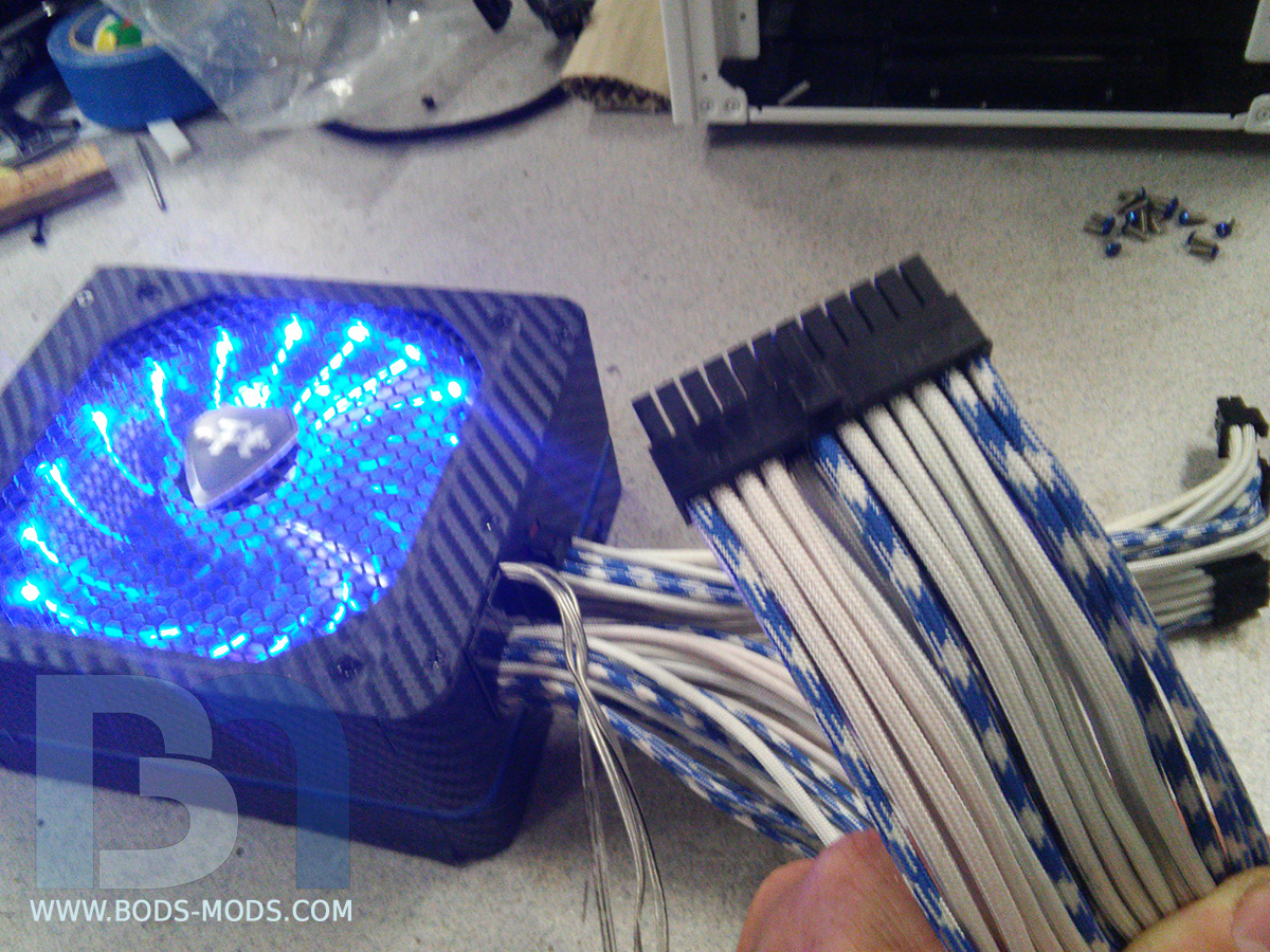
So here's the finished PSU..
ATX 24pin connector. I went with a random look when mixing the sleeve colors, only choosing a few here and there for the blue carbon.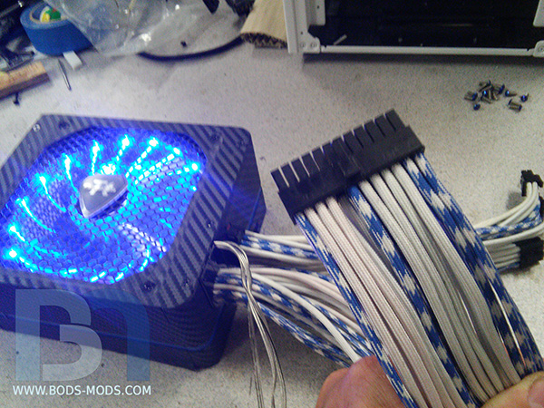
I actually managed to squeeze all the cables back through the stock cable grommet, only cutting a small notch to make room for the Enermax fan cables.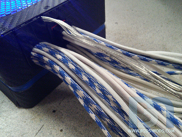
One of the PCI-e cables..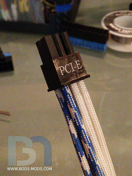
I also tried my hand at sleeving the SATA power cables for the two SSDs.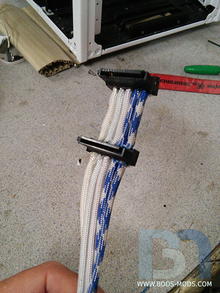
Not bad I suppose. Could be better tho.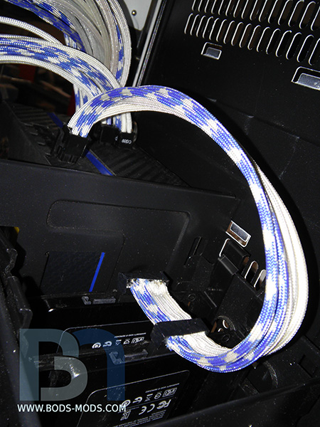
Starting final assembly this week! -
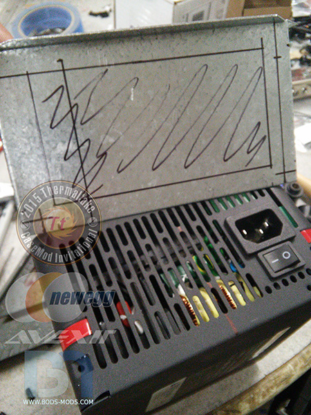
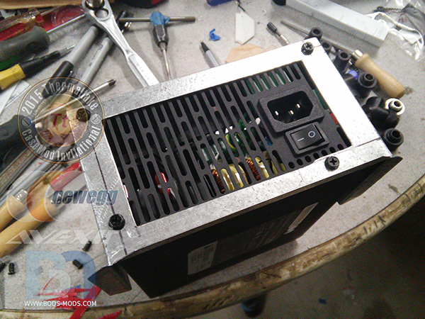
Made some progress on the PSU over the weekend, getting it ready to sleeve.
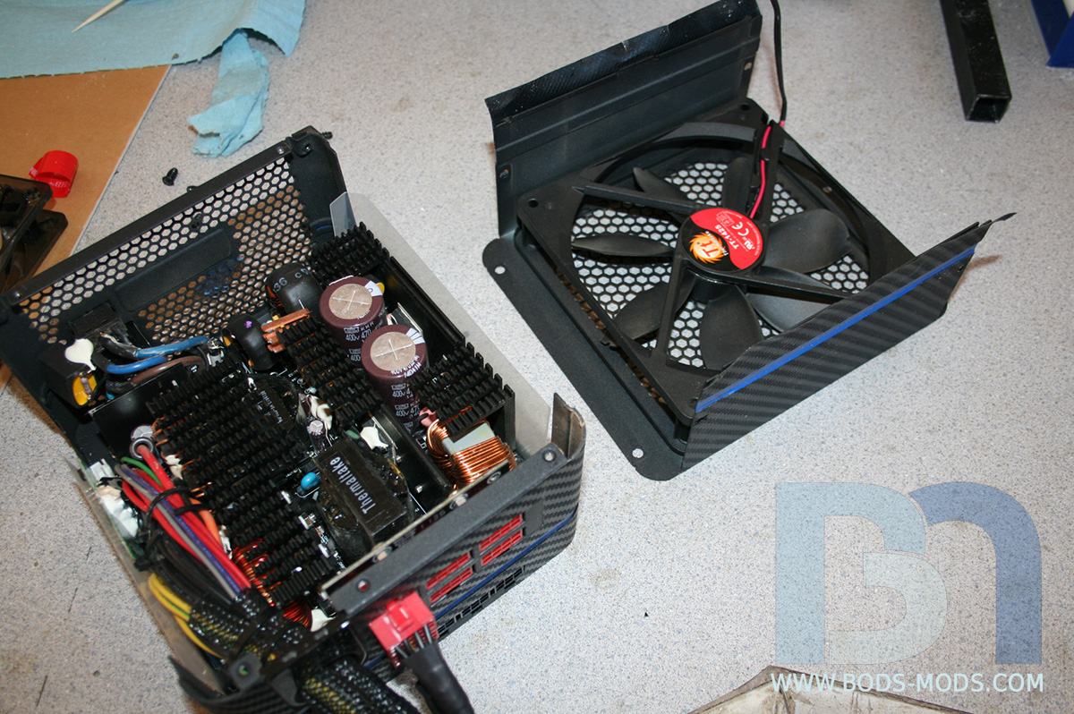
First thing on the list was voiding the warranty...
I've never seen a half fan before..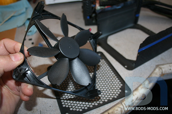
Also first time I've seen Torx fan screws too!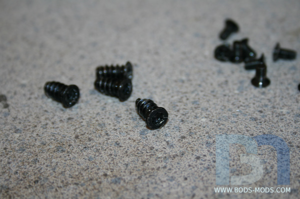
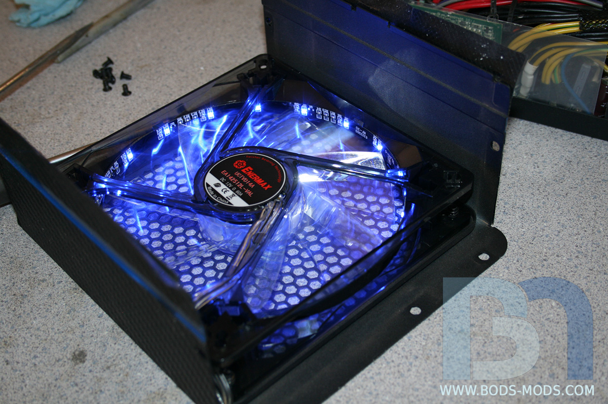
Thankfully, the half fan was a standard 140mm size, so it was a simple change-out for an Enermax Vegas fan. However, the connecter was just a 2-pin, so I'll have to run the wires out of the PSU up to one of the motherboard fan headers. Luckily the Vegas fan has ample cord length, and the PSU is not far from the mobo.
Much better!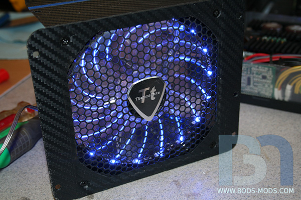
Here's the sleeving I'm going with. Kobra Maxcord from Primochill. Awesome stuff, and the blue-white carbon fits perfectly with the build!
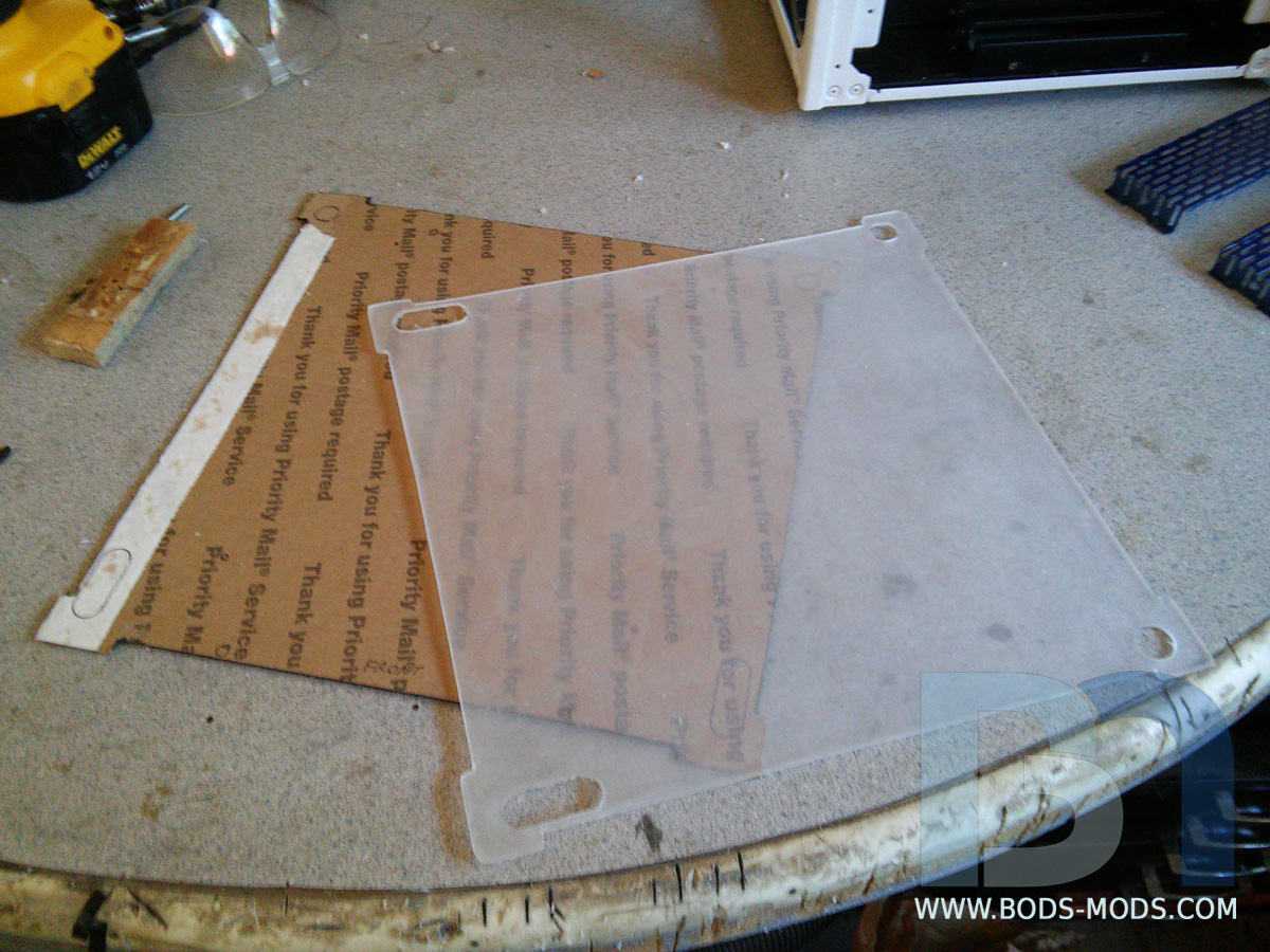
I also got the side panels cut and sent along with the sleeving, but I had forgotten to add some venting in the design, so I will have to manually cut the holes. Using a reference pic of the real R2, I made up a quick template of an inlet and outlet port for both side panels and cut out the patterns.
With the protective paper peeled away, I began cutting the holes.
One side done. Am thinking about adding the Tt logo badge in the center of it..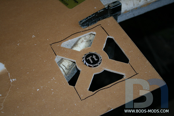
Here's the template for the other side.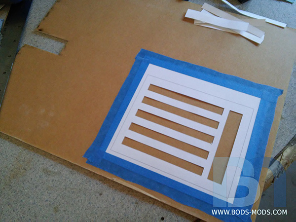
And the other side is prepped for cutting..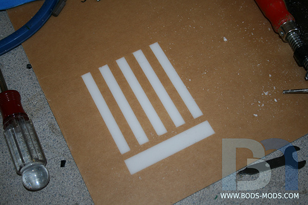
And that's as far as I got yesterday. Will continue on this tonight, and hopefully finish the PSU sleeving this week! -
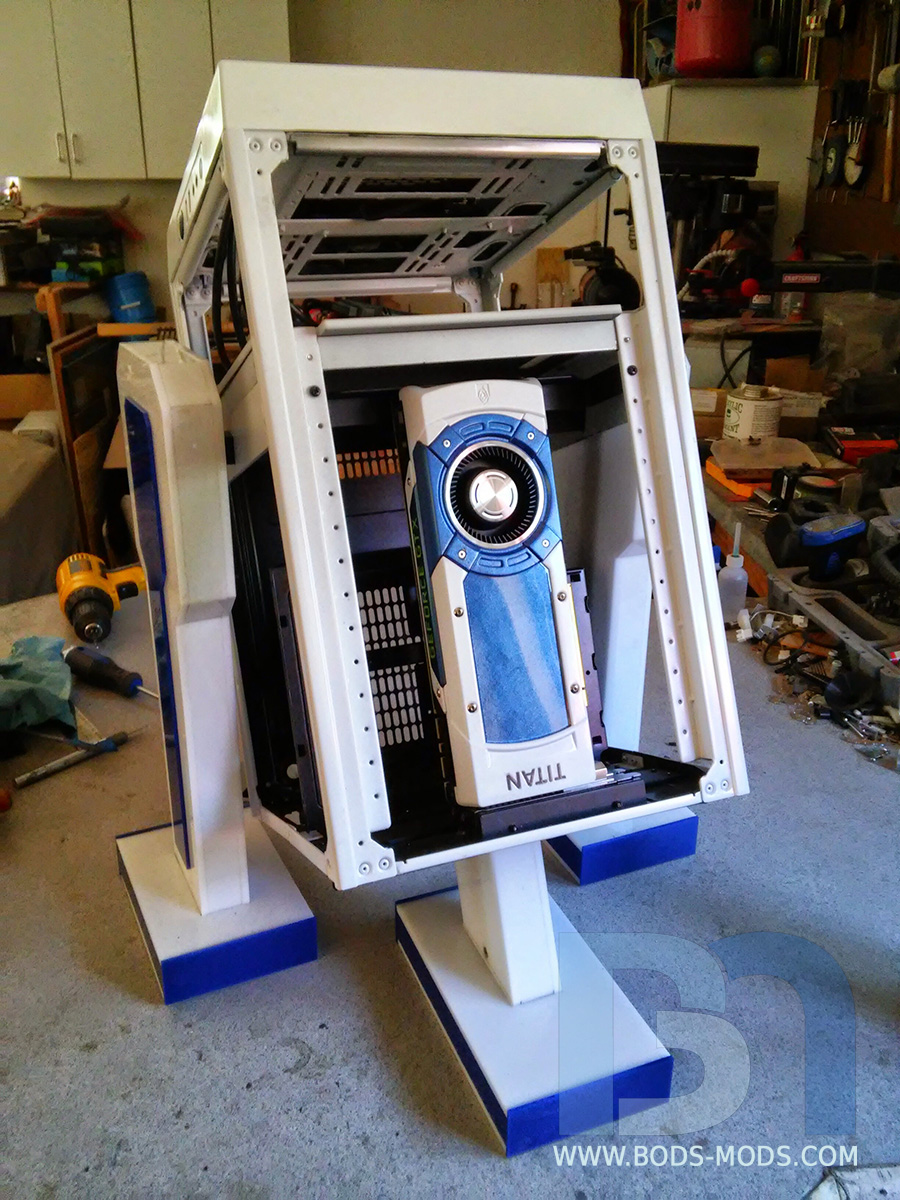
A few more odds and ends taken care of over the weekend.
Here is a closer up view of the leg support system. One 2" flat bar on each side with a square hole in it.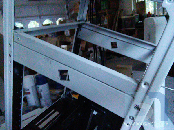
A 1" box tube fits through the holes, and the legs fit onto each end. Wa-la!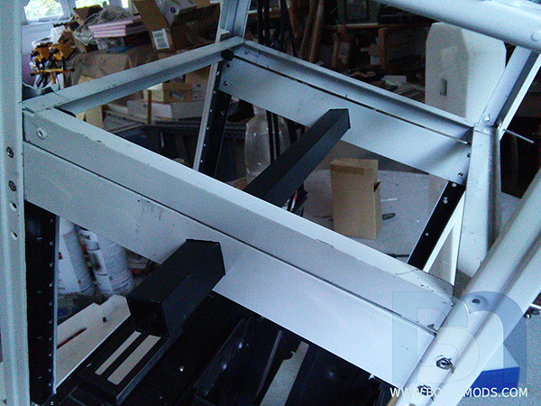
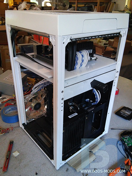
Figured I'd throw it all together and see what it looks like so far..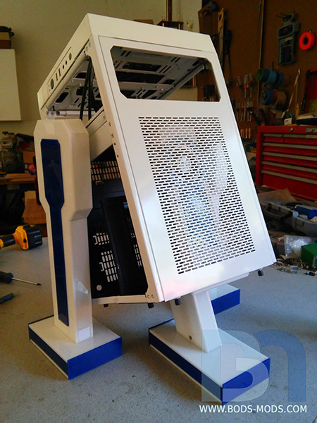
and with the front panel off to show the video card. Must do something about that unsightly ceiling area tho..
So I made a cardboard template and cut a piece of acrylic to fit up in there.
After making a few adjustments and figuring out how to fasten it into place, I painted the backside metallic blue. Looks pretty good! I'm digging the reflection, and it will look even better once the hardware is mounted.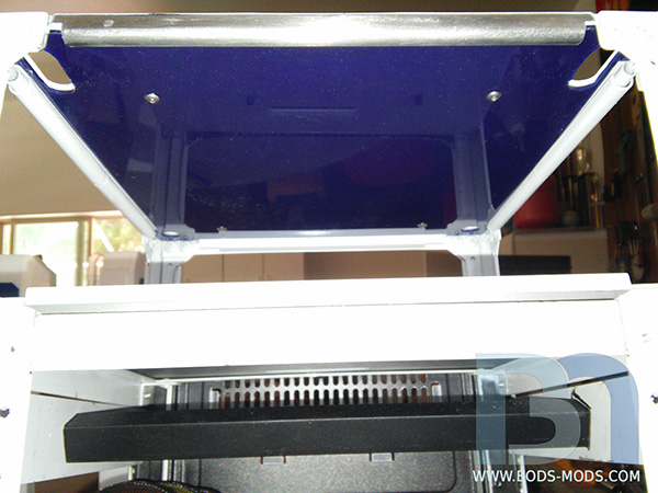
I've got one more set of brackets to make, and the fabrication is done. Just have to figure out the mounting of the 120mm radiator for the AIO cooler. Then it's on to sleeving the PSU.


[USA] Brian Carter
in 2015 Thermaltake CaseMOD Invitational Season 2
Posted
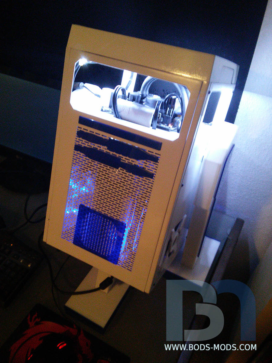
Ok here are the final shots. I'll be doing a more proper photo shoot later, but I had to get final pics up asap.. So here they are.. Enjoy, and thank you everyone for following my crazy concept to fruition.
Here is the voting link. Please head over to check out all the excellent builds, and vote for your favorite!
Thank you Thermaltake for the nomination, it was great to be included amongst all these amazing and talented modders! Everyone's mod was completely different from each other's, it's a testament to how versatile the Core X9 case really is, and it only reinforces the basic idea behind my theme.
Special thanks to Avexir for providing the memory, Primochill for all the laser cutting and sleeving, Newegg for providing all the great hardware, and of course Thermaltake for pretty much everything else! Congrats to all for a great competition and best of luck! Can't wait to see who wins!