-
Forum Statistics
7.5k
Total Topics50.9k
Total Posts -
Member Statistics
135,999
Total Members16,800
Most Online


BigWookie
-
Posts
6 -
Joined
-
Last visited
BigWookie's Achievements
Beginner (1/10)
0
Reputation
-
Hello again, I can't find a good picture of the ARGB cable so I'm guessing which end you use depends on which connectors your motherboard has available. What motherboard are you connecting to? Glad to help and take care, Matt
-
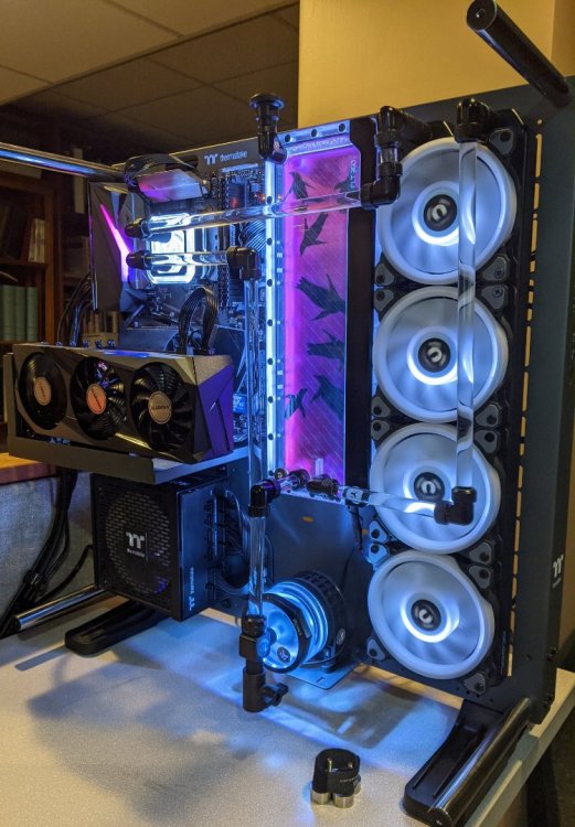
Nice looking rig! Do you notice Windows chirping that noise it makes when USB devices are added/removed from the system when the lights suddenly turn on like that? I use a cheap KVM to switch between my personal PC and my work laptop which means my USB keyboard is constantly being added/removed from the system. I believe this type of event causes some sort of noise or scan on the USB bus and the TT software doesn't like it. I downloaded USB Tree View to start learning more about what's going on in my USB world but I haven't gone down that rabbit hole yet. Here's mine while playing some music so the RGB in Party mode is flashing the lights.
-
Hi there, do you still need help with this? If not, no big deal and I'm glad you figured it out. If so, I hope this helps. I'm reading the doc for TOUGHPOWER PF1 ARGB - 850W part # PS-TPD-0850F3FAPU-1 From left to right, top to bottom: The first connector is 8 pins and is labeled 4+4 CPU & 6+2 PCI-E The second connector is also 8 pins and is labeled 4+4 CPU & 6+2 PCI-E The third connector is part of the 24 pin motherboard connector and has 18 pins The fourth connector is also part of the 24 pin motherboard connector and has 10 pins both of them are labled 24 PIN ATX Moving to the second row The first connector on the second row is another 8 pin connector labeled 4+4 CPU & 6+2 PCI-E The second connector on the second row is also 8 pin labeled 4+4 CPU & 6+2 PCI-E The third connector on the second row is 6 pin labeled Peripheral and SATA The fourth connector on the second row is also 6 pin labeled Peripheral and SATA Moving to the third row The first connector on the third row is another 8 pin connector labeled 4+4 CPU & 6+2 PCI-E The second connector on the third row is another 6 pin labeled Peripheral and SATA The third connector on the third row is also 6 pin labeled Peripheral and SATA There is one more connector on the power supply that isn't really part of a row or column. It is all the way to the right side of the P/S and has 3 pins vertically. This is the ARGB Sync connector that goes to your motherboard ARGB header. Good luck with your build and take care! Matt
-
Hi there, I've been very frustrated with TT software over the last few months too. I bought a 4 pack of Ring Quads and they didn't work right out of the box. TT replaced the controller for me and things got better. In my build I have all 4 fans connected to the RGB controller and then the controller is the only thing attached to the molex connector from my power supply. If I add any other devices to the power connector my machine won't even power on. I currently believe it is a power draw issue because everything works just fine if I move the other devices to a different power connector. And by different I mean an entirely separate power cable, not just a different molex connector along the same power cable - if that makes sense. I wonder if you're pulling too much power through a single peripheral/sata power connector on your P/S and that's why the RGB isn't lighting up. Can you get it to work with just 6 fans? Sorry I don't have a more precise solution for you but I thought I'd offer my advice and encouragement. Stick with it and I'm sure you'll figure it out.
