-
Forum Statistics
7.4k
Total Topics50.6k
Total Posts -
Member Statistics
135,784
Total Members16,800
Most Online


Inony
-
Posts
30 -
Joined
-
Last visited
-
Days Won
8
Content Type
Profiles
Forums
Downloads
Events
Gallery
Blogs
Posts posted by Inony
-
-
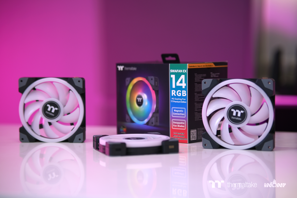
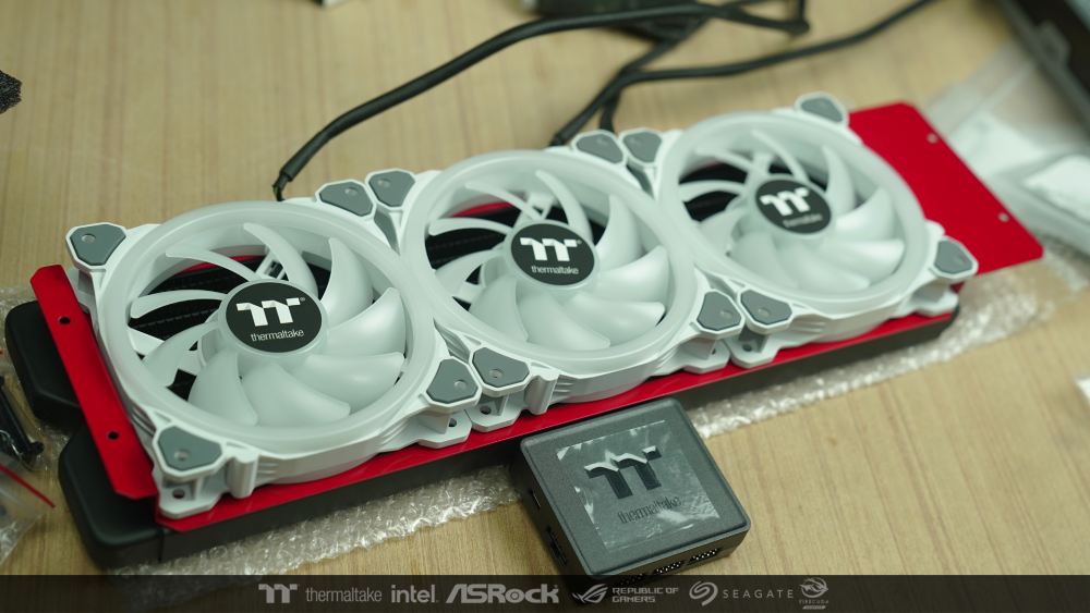
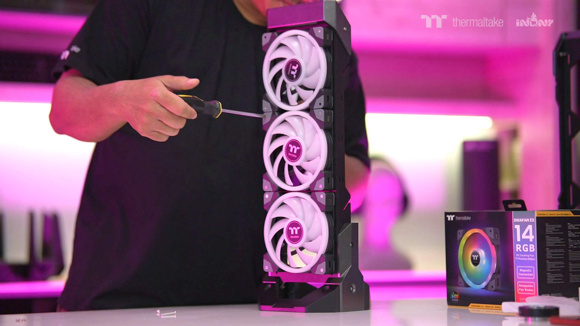
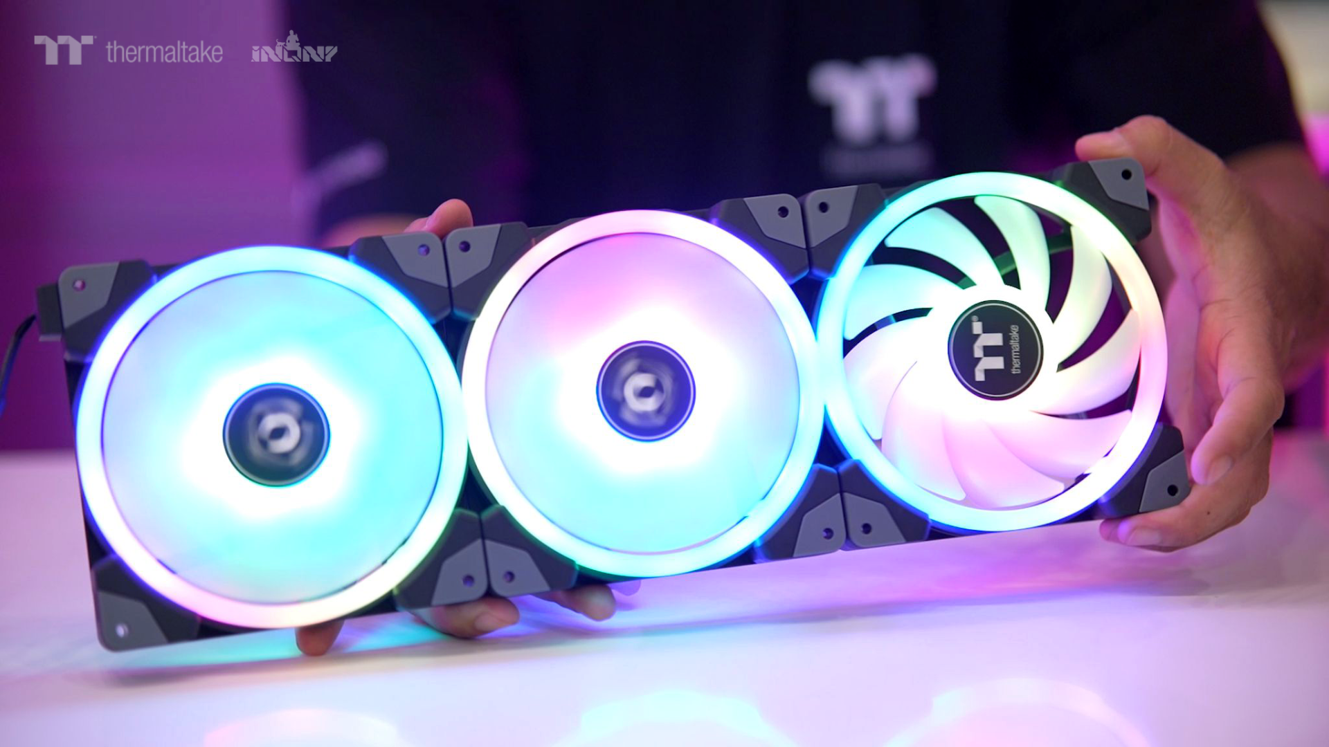
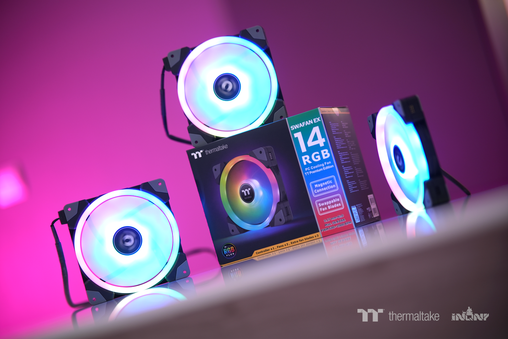
In the profile of the fan light. I think it will be presented in a pack of 3 through a display stand.
I refer to the actual installation from the case, which is mostly the fan installation area. We usually put 3 on either the front or top.
So I designed a simple stand . My display pack 3 fans for presentations.
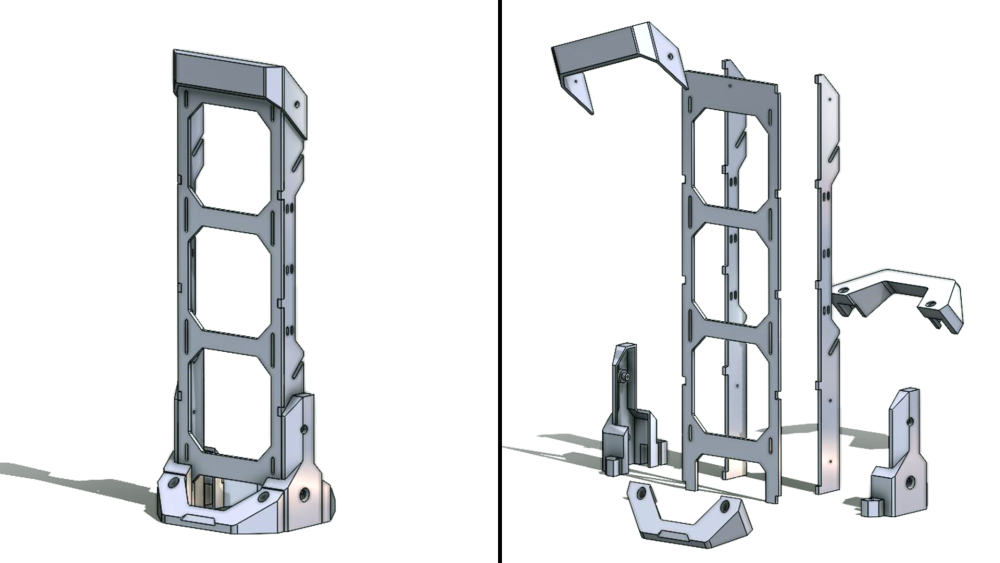
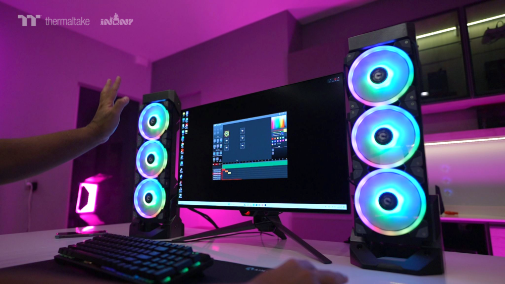
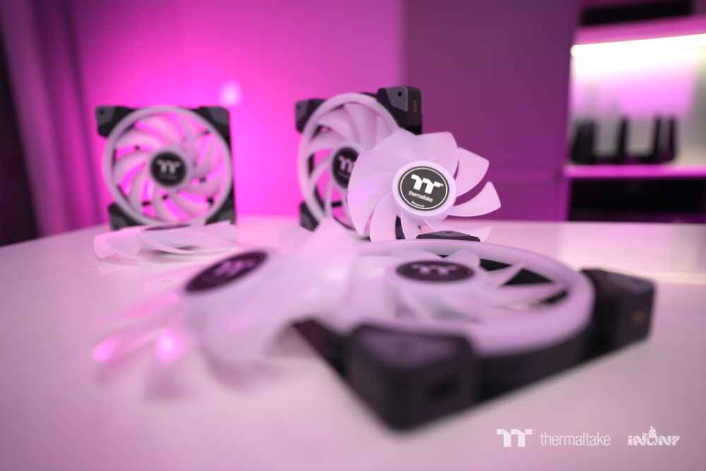
I installed all 3 fans and used all 3 connection cables form the bundle box. I separate them from each other for feel free to make light steps.

Then I started working on all 15 profiles. It didn't take me long to learn. The program is very easy to use.
Now I've done it and I'm editing the video for the presentation.
Creating a light step was a very fun experience. Thank you very much for inviting me to participate in this competition.
-
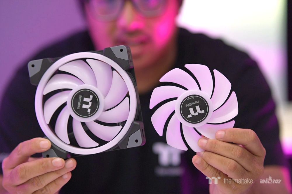
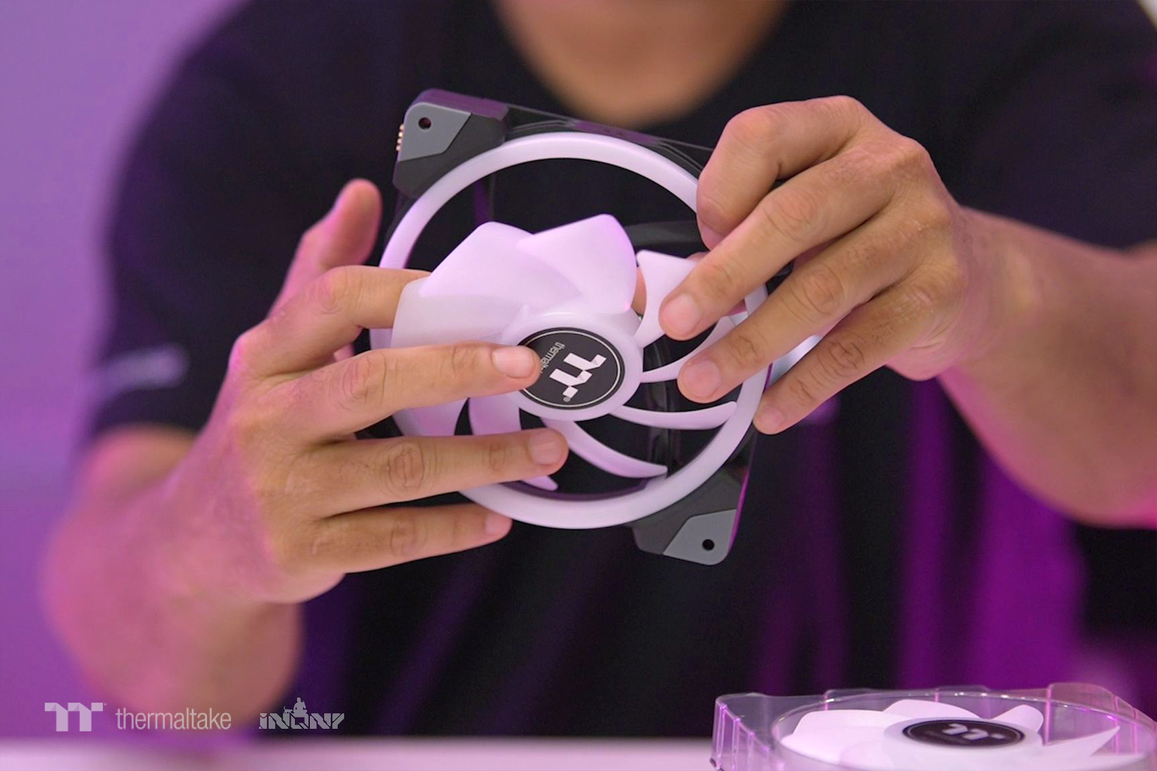
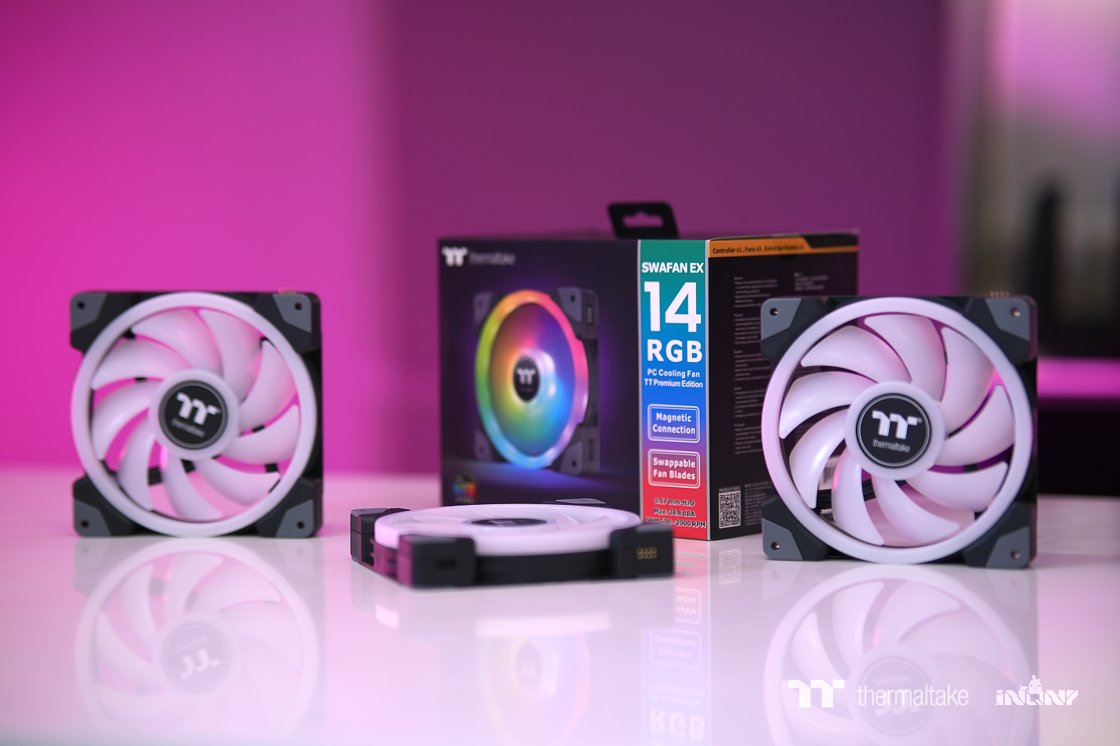
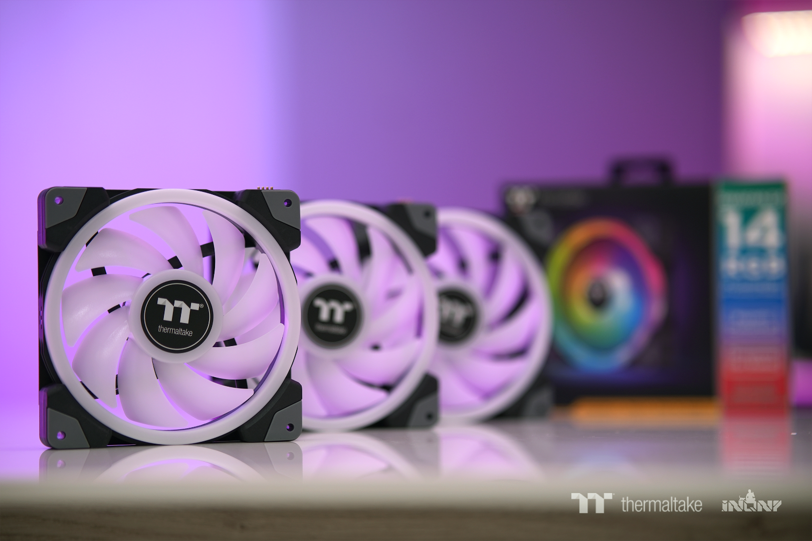
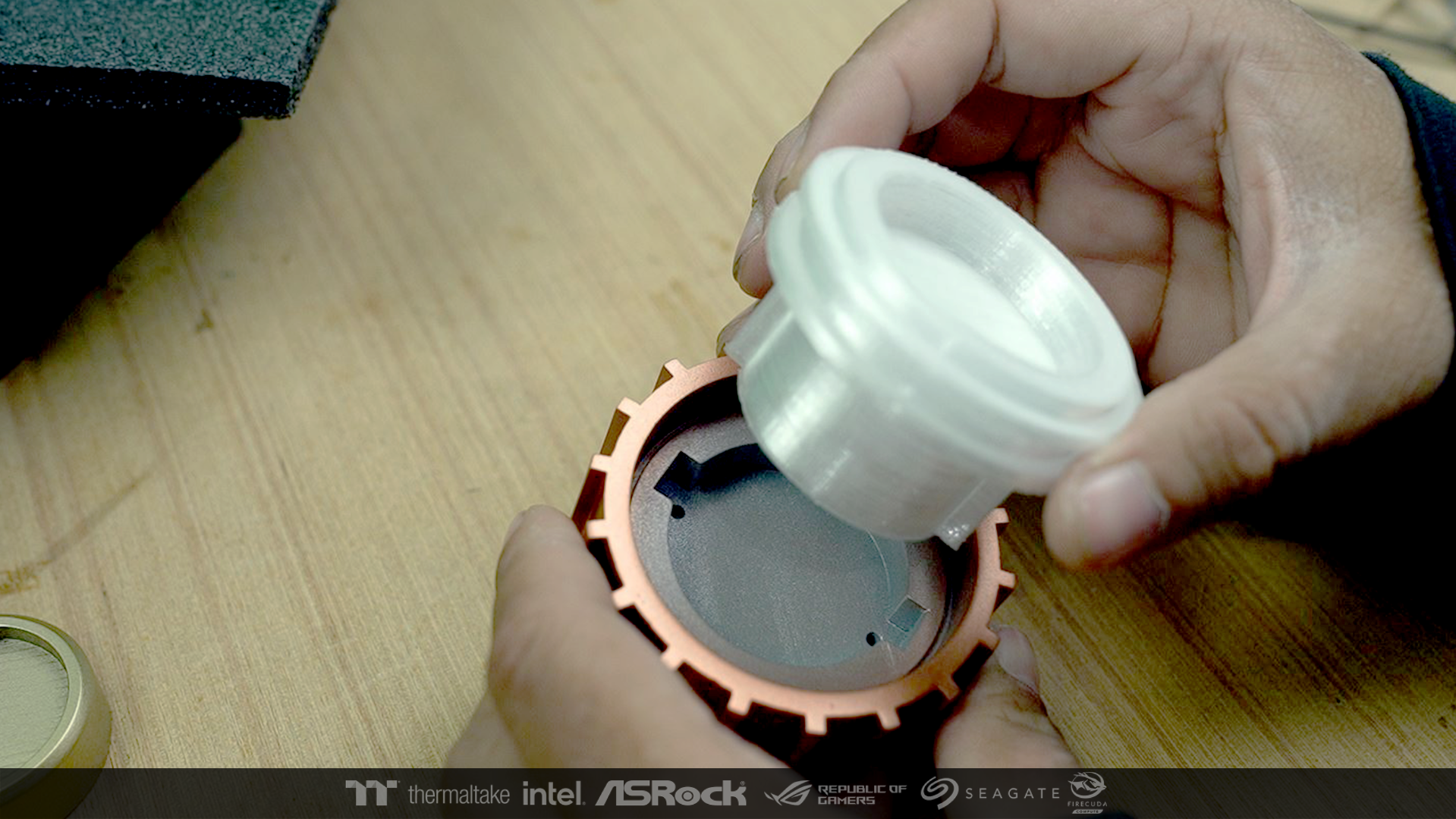
I tested everything in the usage section. Changing fan blades is easy.
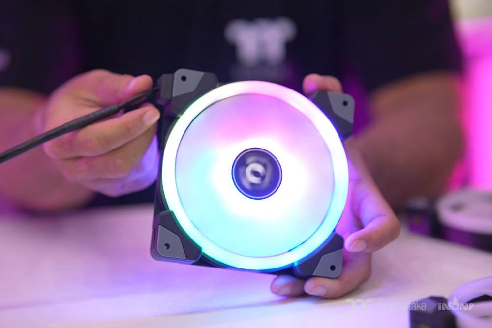
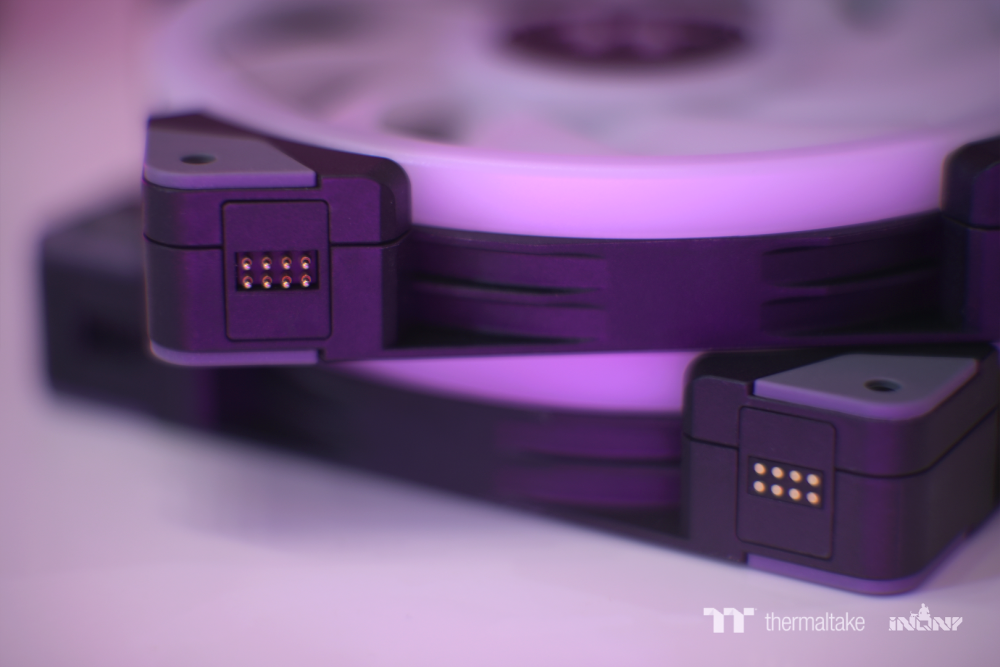
The connection from wires or from the fan to another. The magnets make it easy and I really love it.


-
Hello everyone,
I would like to thank you for the honor of inviting me to participate in this competition. I've never join in this type of competition before.
It was a very good experience for me. This program is really funny than I thought.
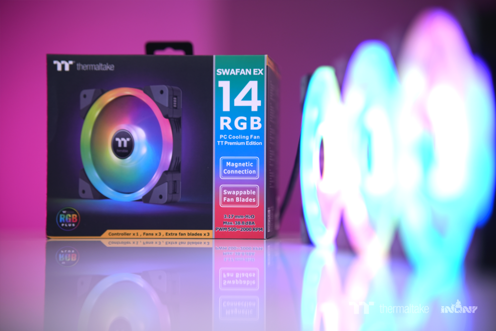
The main product used in this competition, SWAFAN EX14 RGB PC Cooling Fan it looks very cool.


-
-
-
-
-
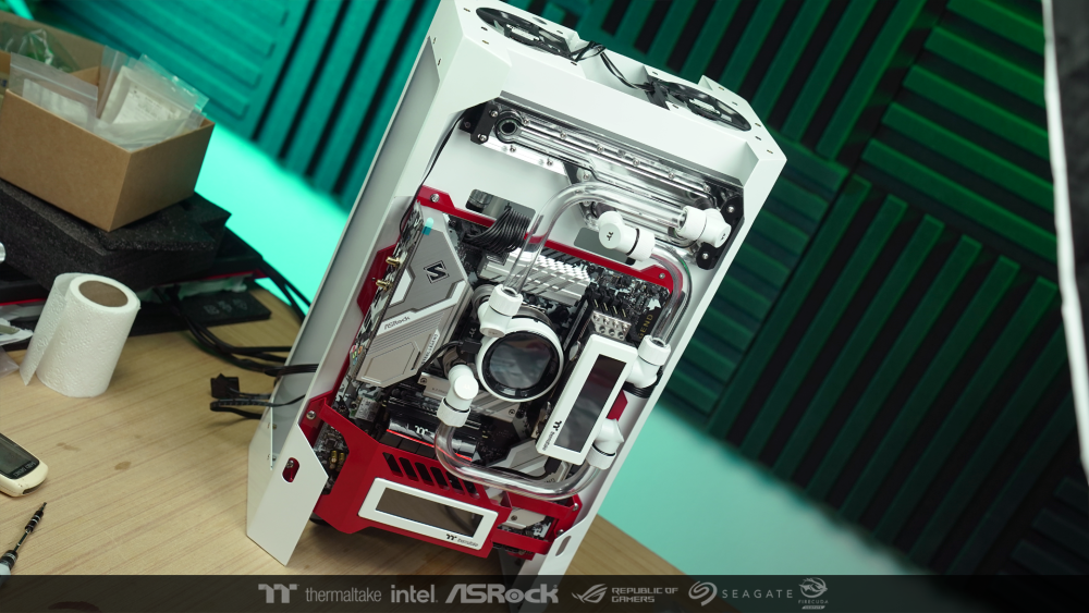
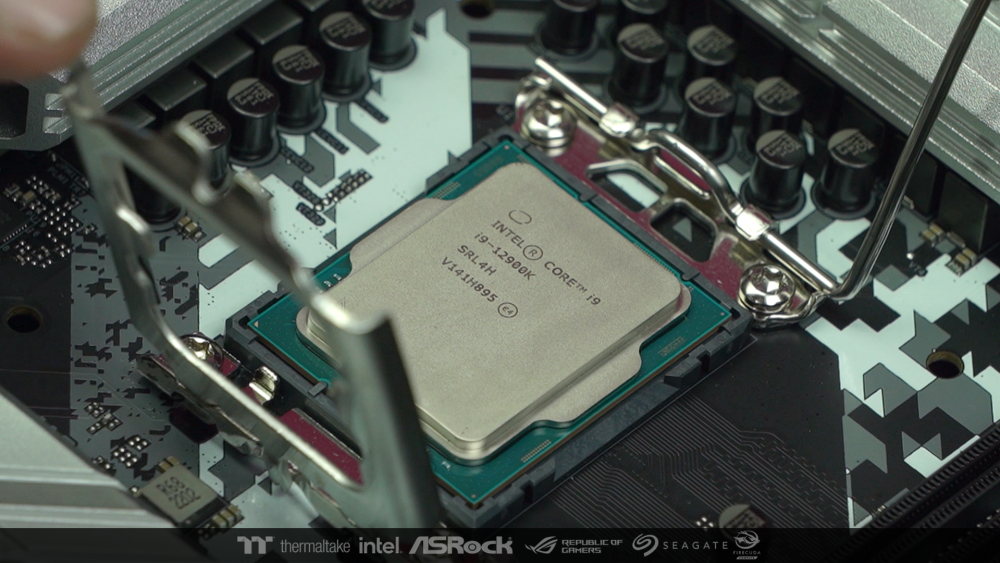
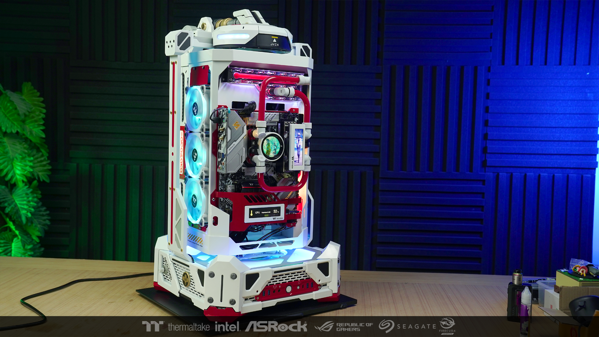
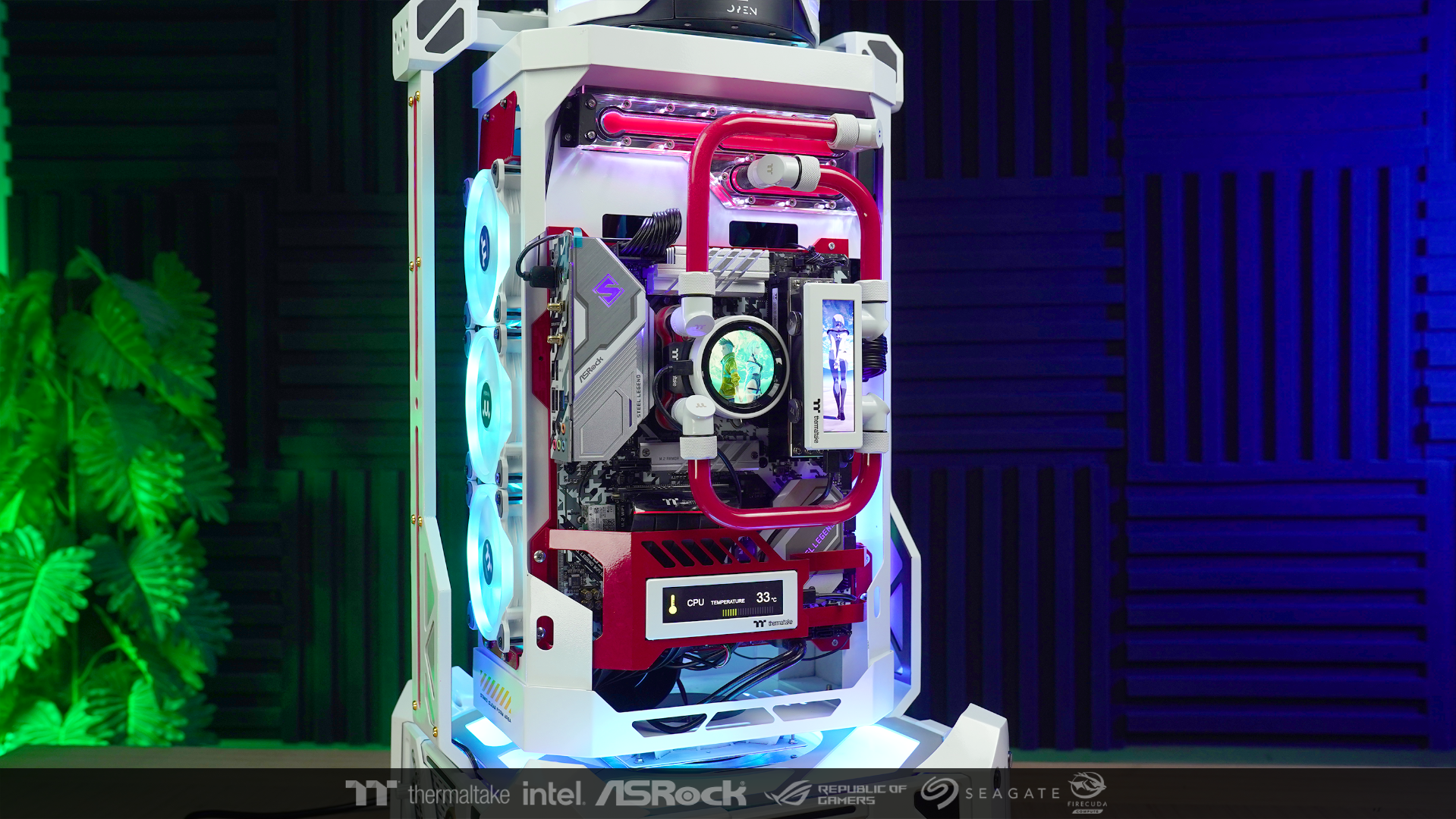
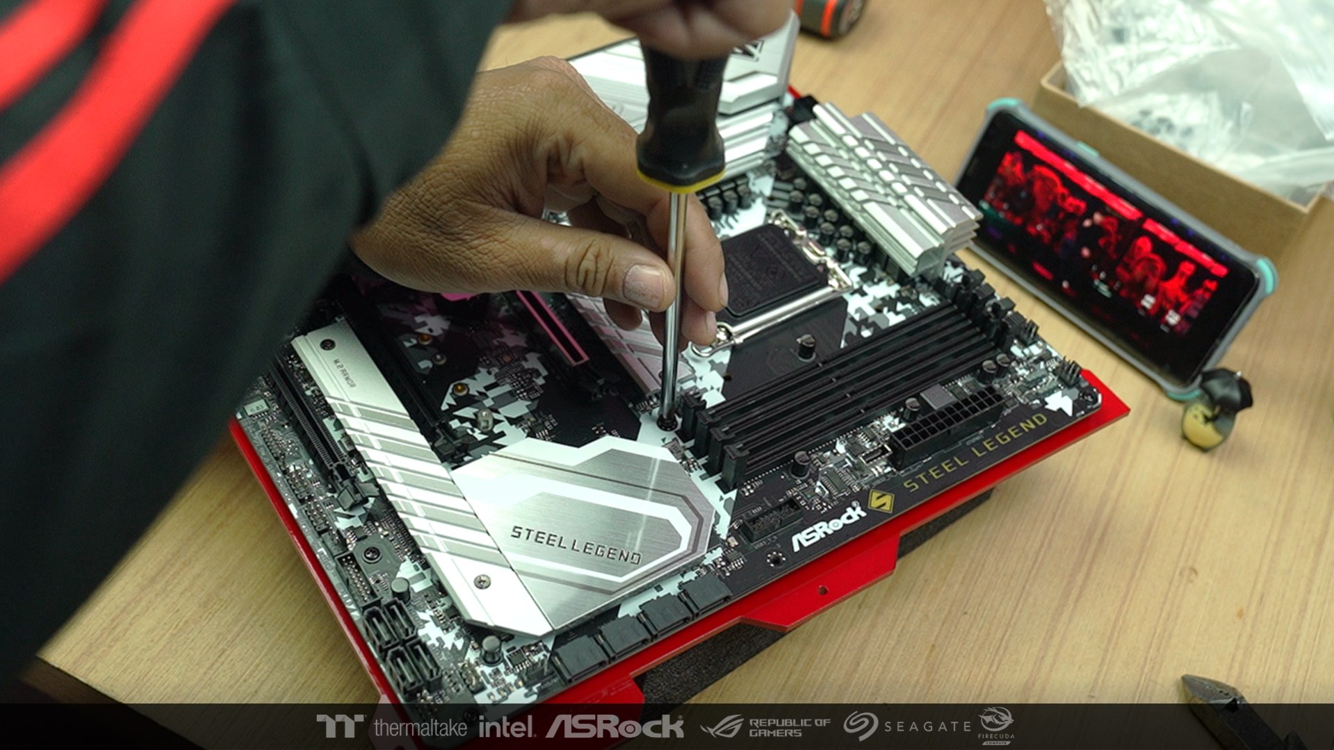
When all the pillars are already installed So I started installing the rest of the hardware.
And start connecting the wires from the various paths that have been prepared before.

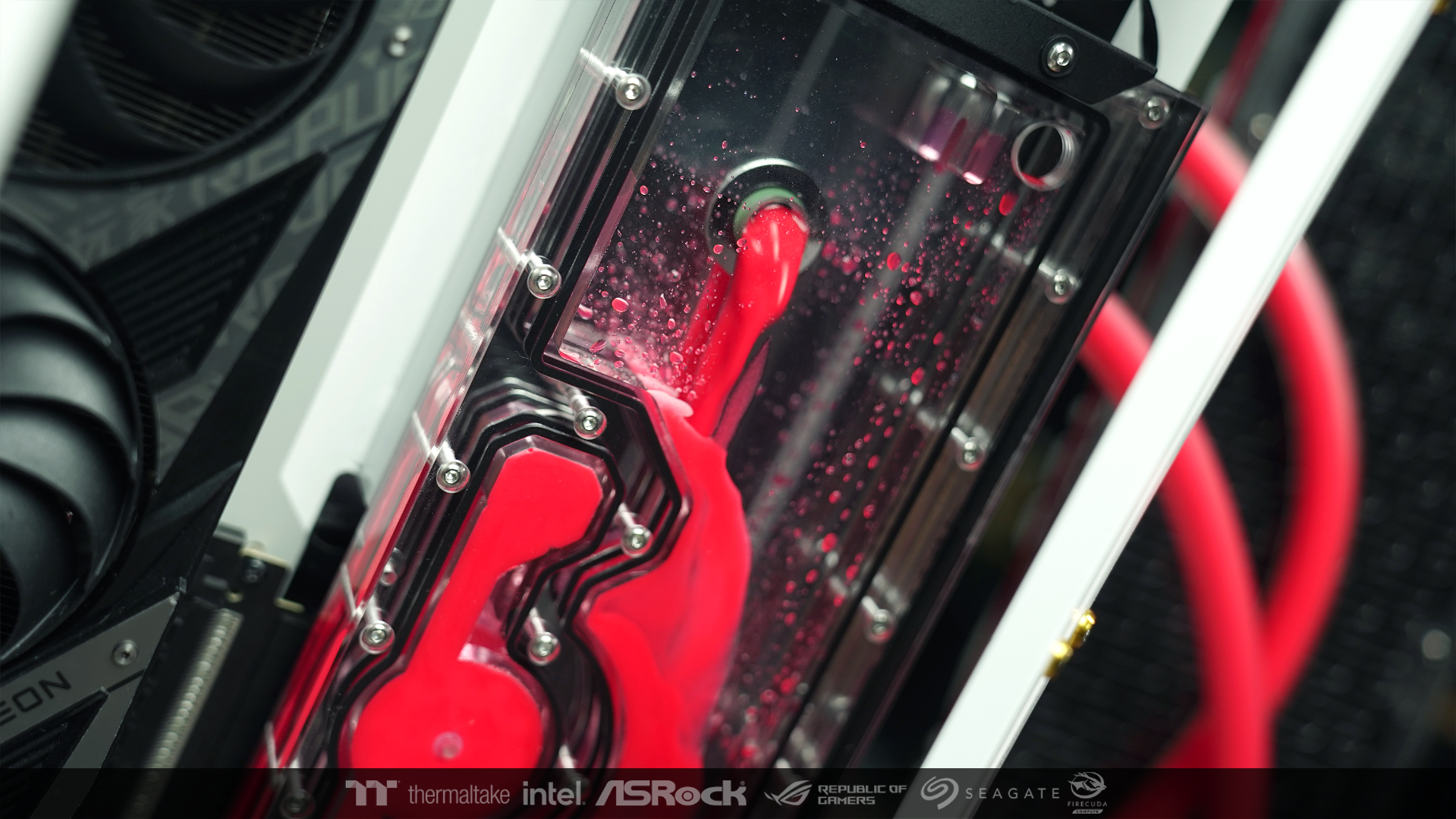
After that I added water to the main system to check it wouldn't leak.
I left the pump to run for an hour until I was confident.

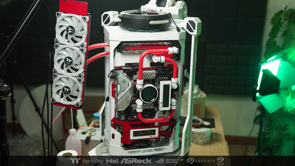
After that, I connected the whole system together to final test.
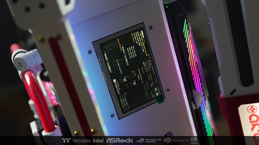
Now I can see BIOS from the small screen that I installed. it means Everything works great.
All hardware is fully detected and correct. After this, I will probably install windows and Tt software.
For the other steps, I probably won't update. See you again when the work is finish.
- waii, Intellence and Andrew Makin
-
 2
2
-
 1
1
-
13 hours ago, Andrew Makin said:
Incredible work 💜
I look forward to admiring your work and everyone. It's near the deadline now. Good Luck , Bro 🙏 ☺️
-
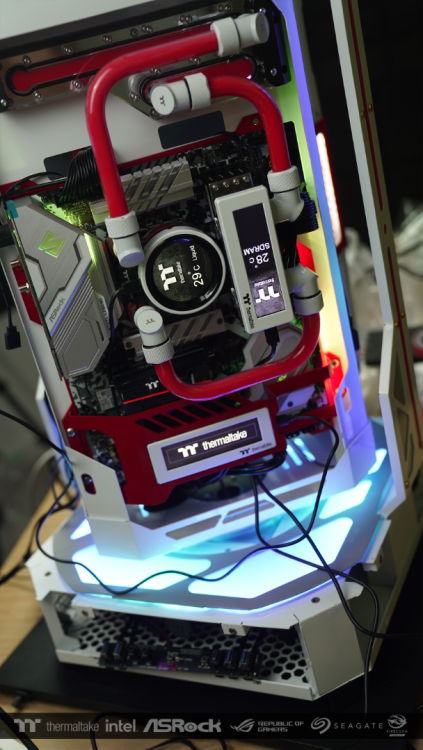
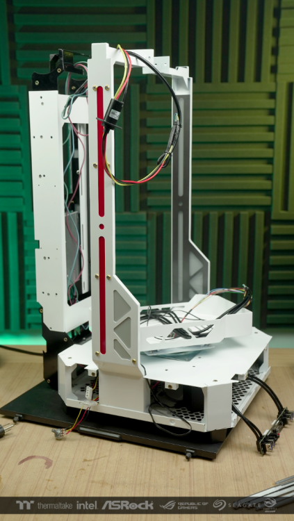
When everything is fine So I started putting the parts together to finish the job.


-
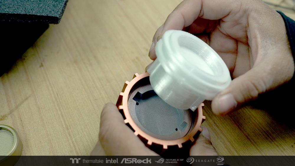
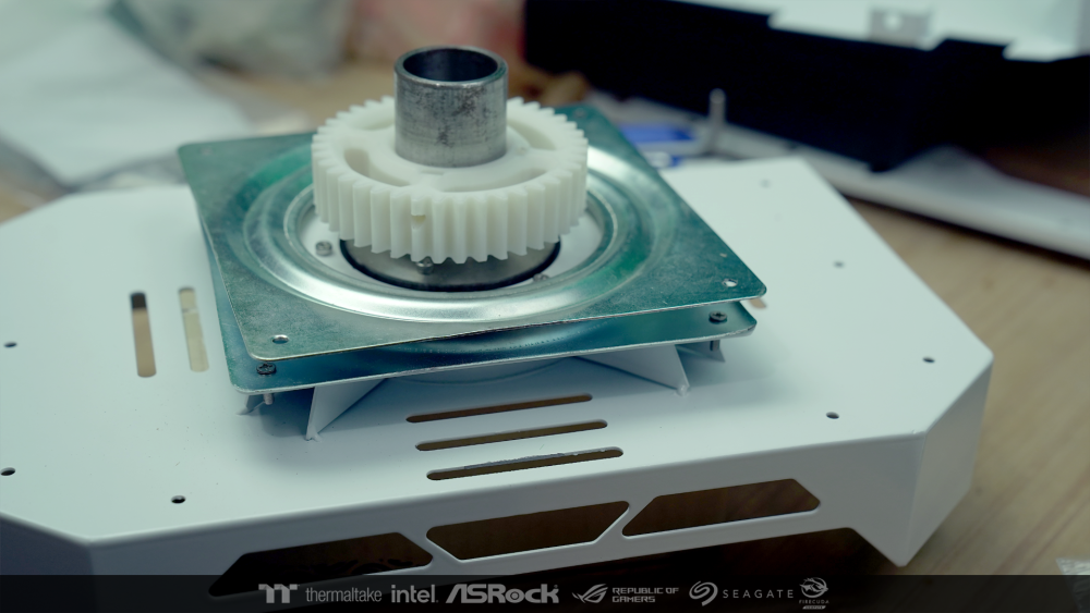
After that, start assembling the gears. In the base part of the hardware installation area.
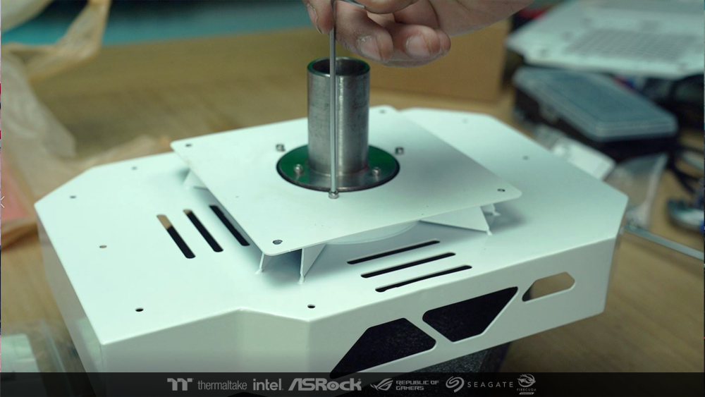
I connected the signal cable from the original Front Panel through the Slip ring.
Everything from the bottom was still connected and works fine even though the upper part is spinning
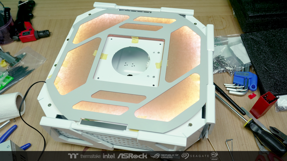
After that, I came to complete the part and Box Light in the pillar part. and install test lights to check the accuracy.

-
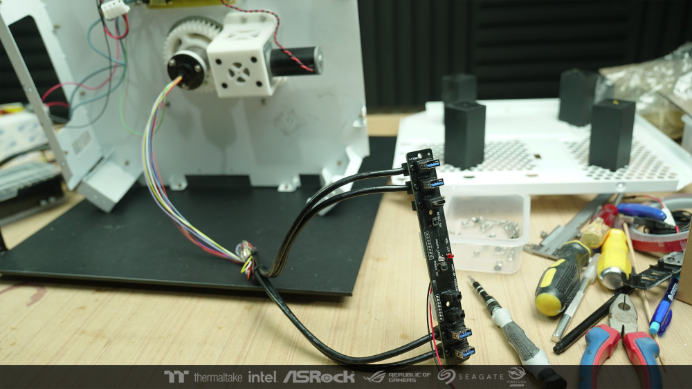
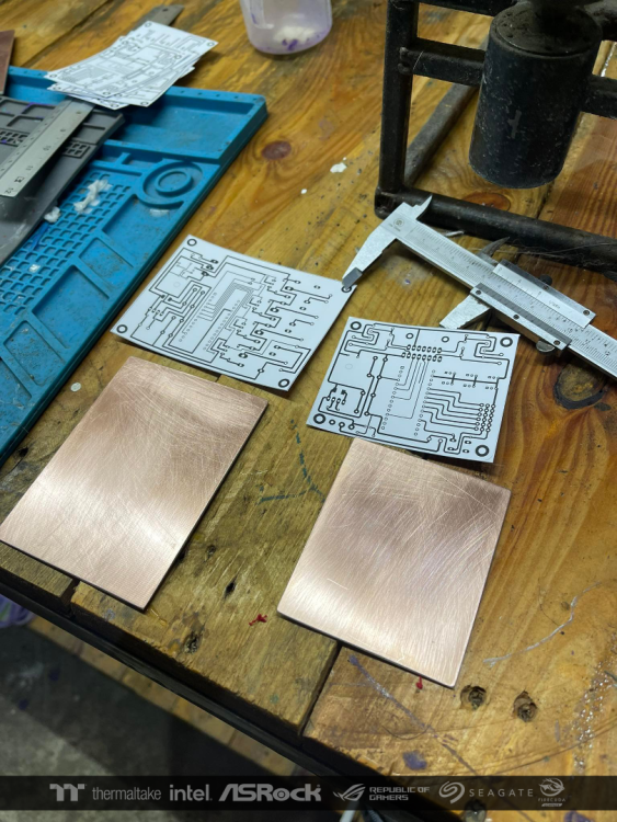
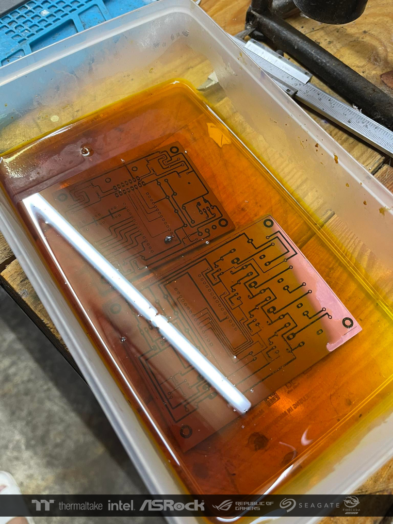
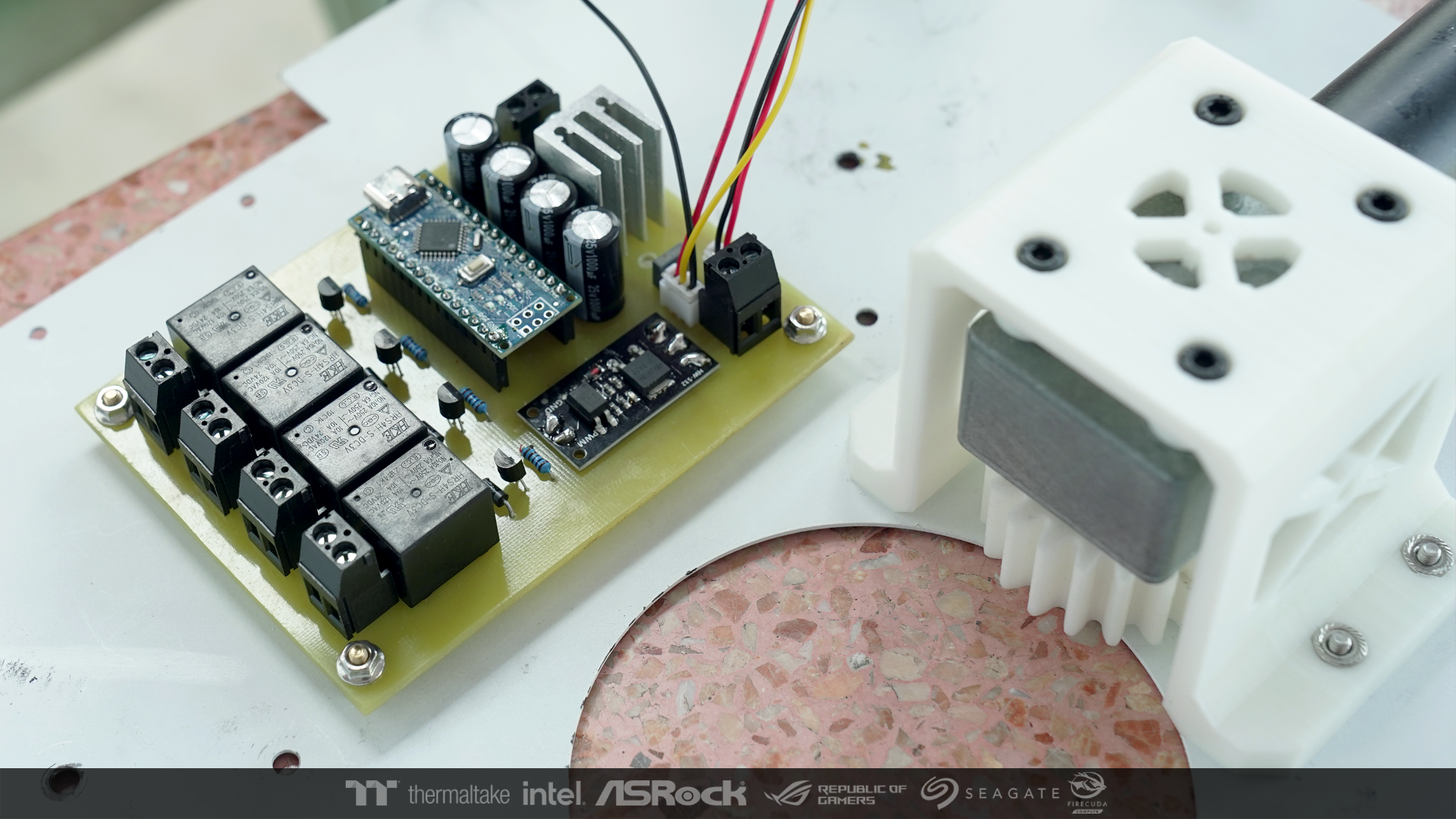
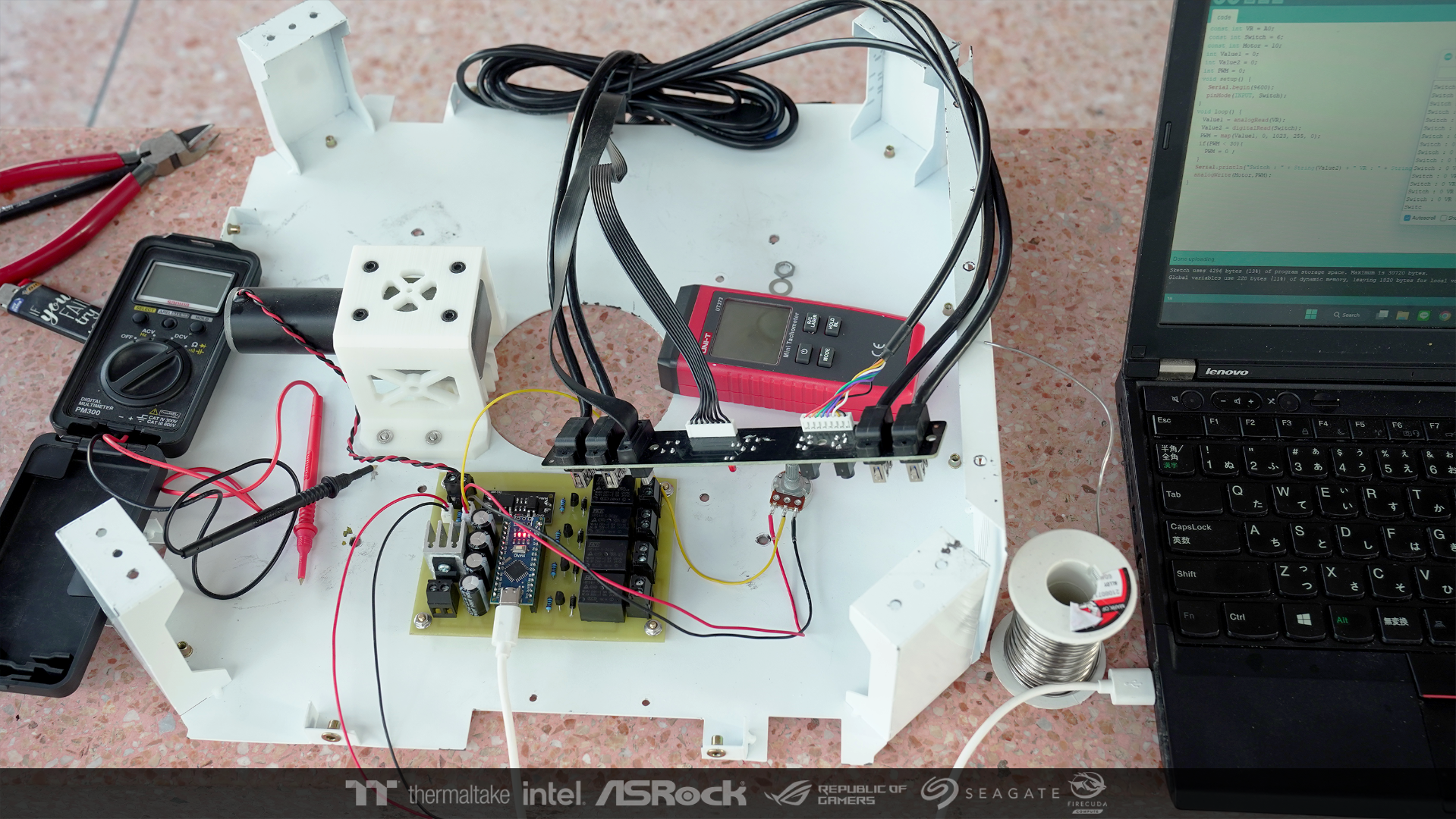
After the base is finished. I moved on to work in the power and control unit.
I made two small control boards. One is for control USB HUB and the other one is for motor control and the power supply order.
Here I will show the control board first.

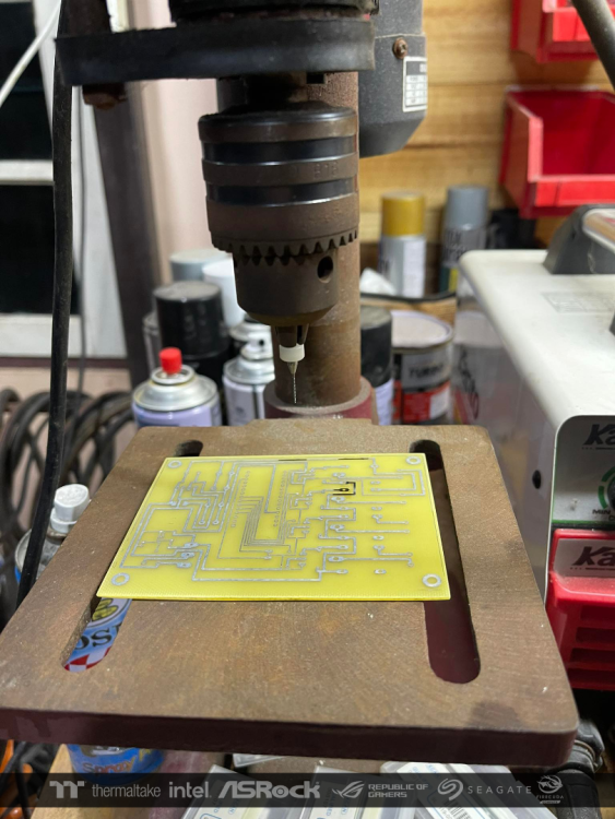
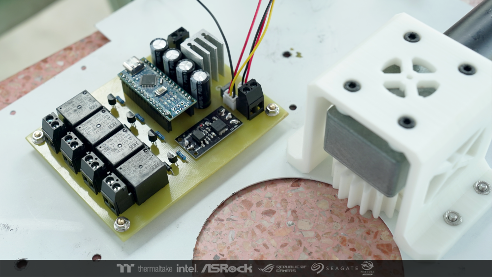
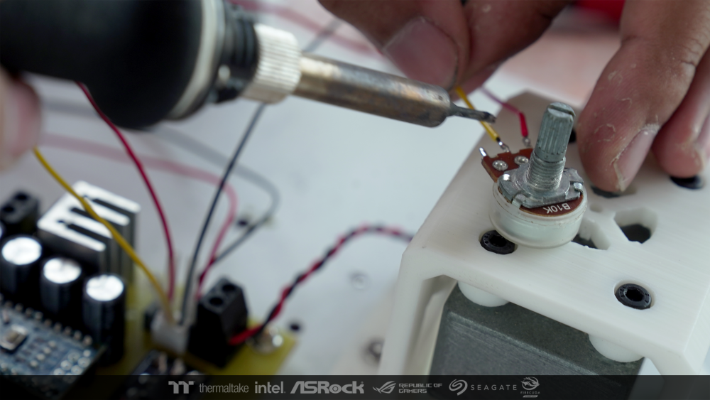
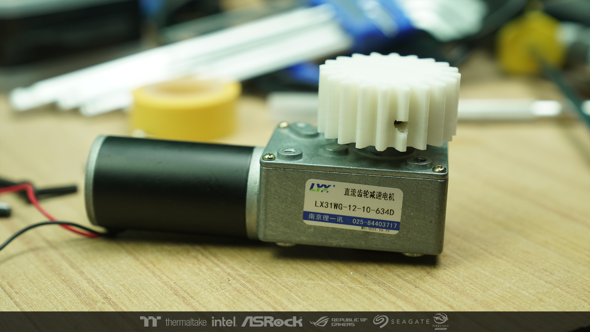
I made a separate swiss to control the speed of rotation of the motor which I had already tested gears ratio.
Power from AC will come to this board first. Through the power button from the original front panel.
and then separate to order the 2 PSUs at the bottom and top to work at the same time.
I delayed start at each point of LED / Fans a / Motor a bit to get that sci-fi feel.

-
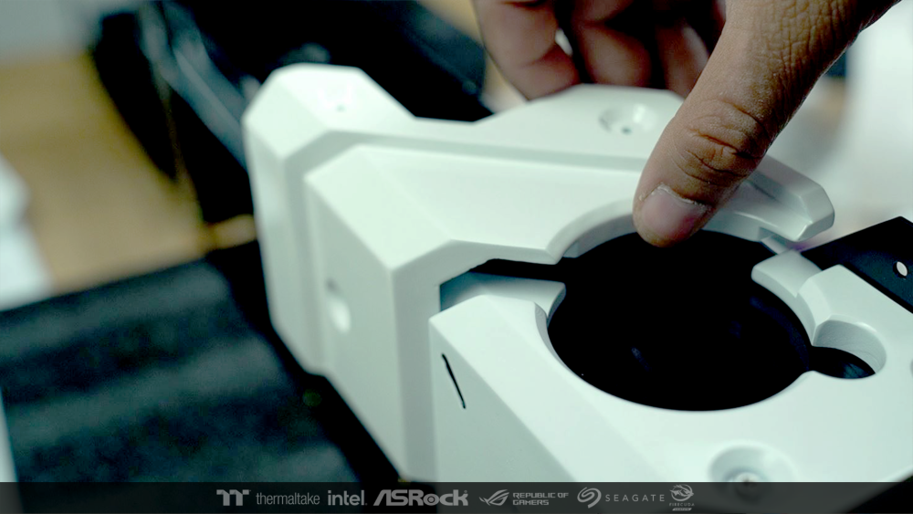
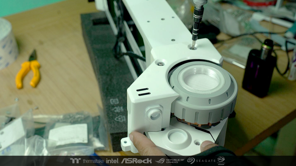
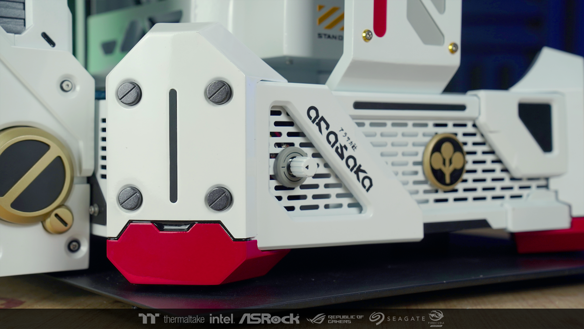
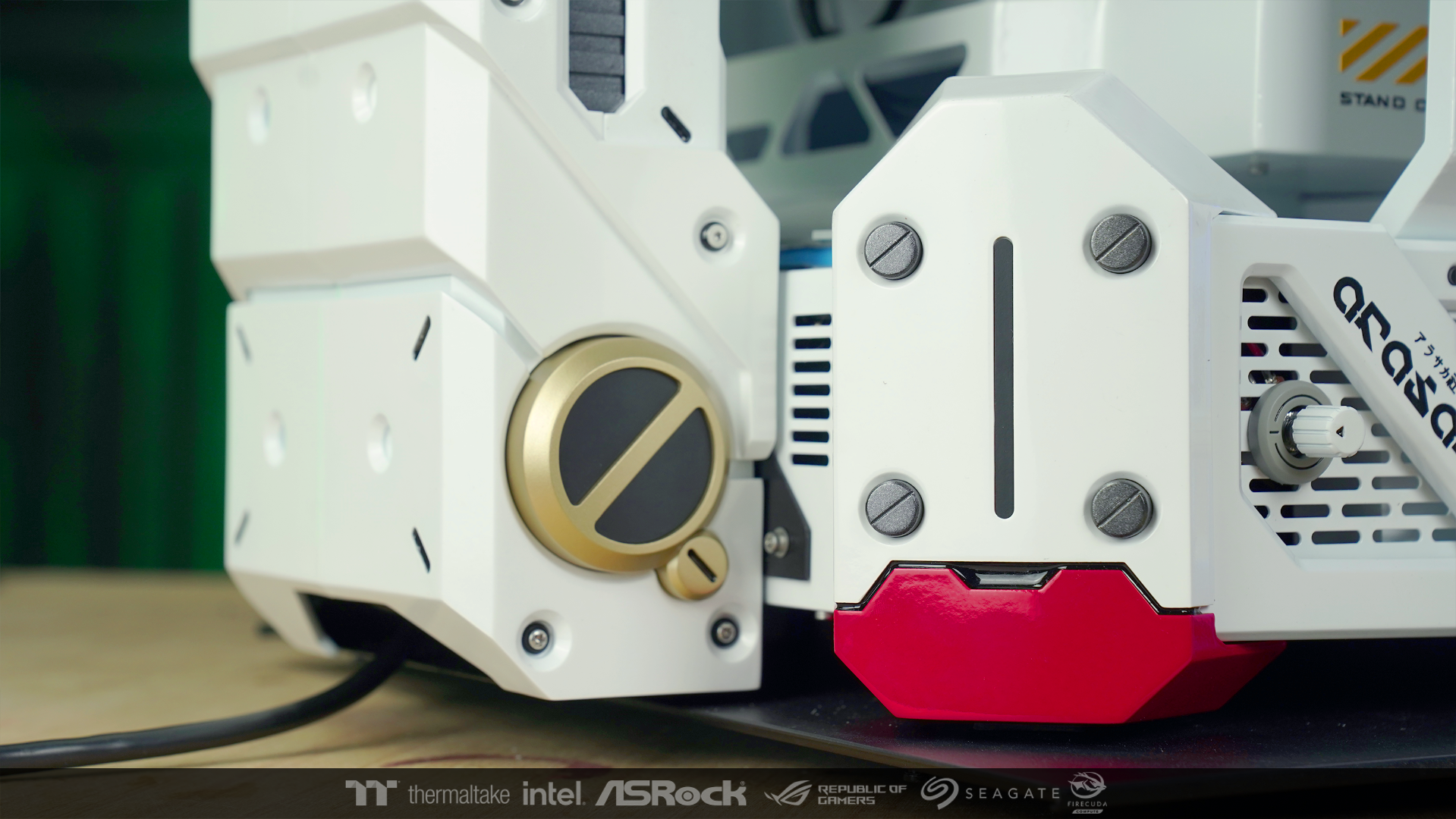
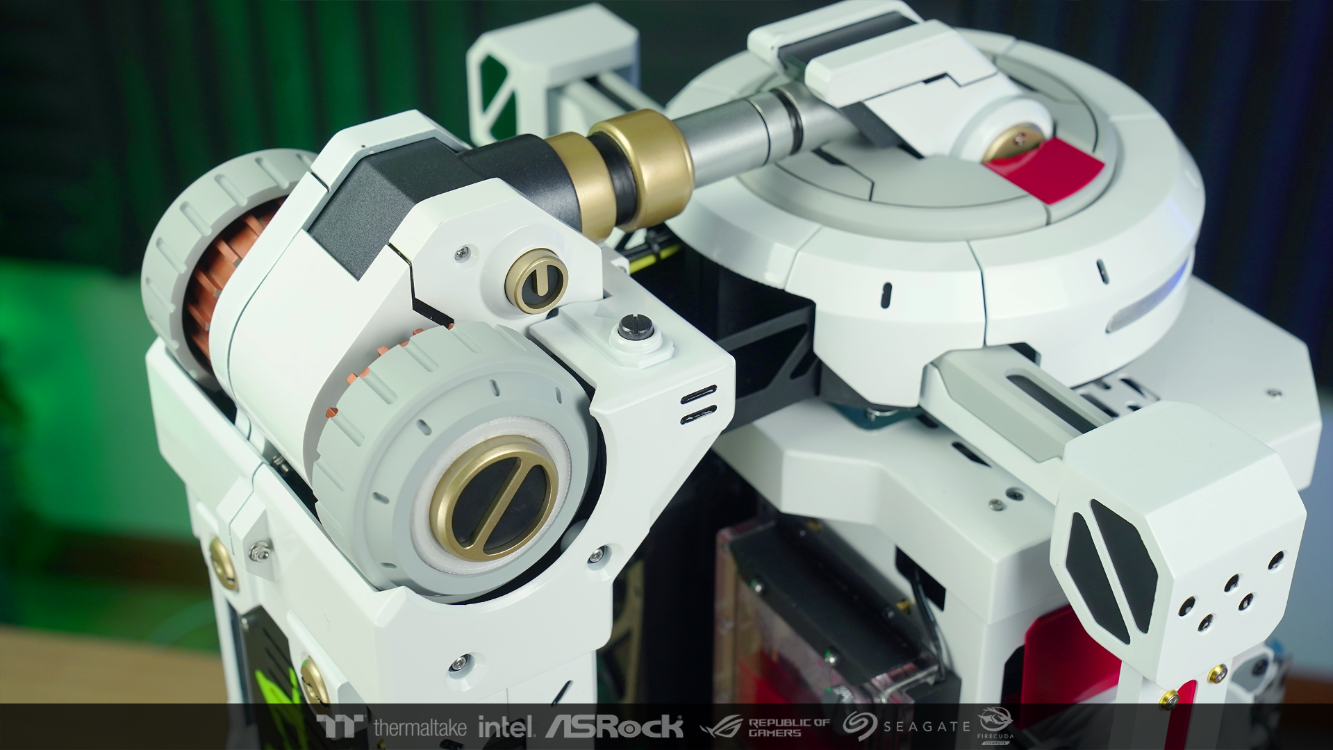
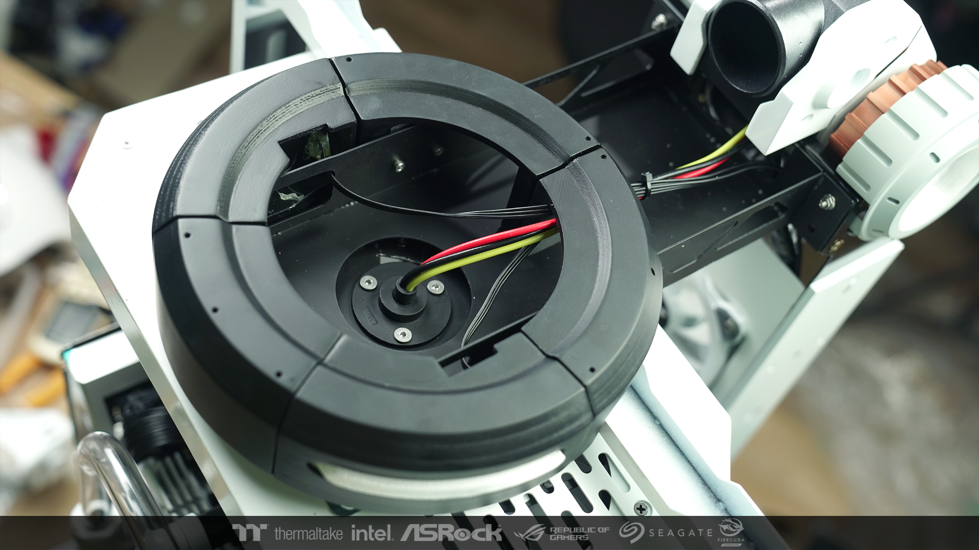
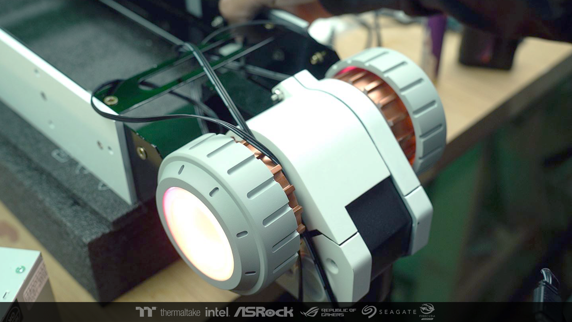
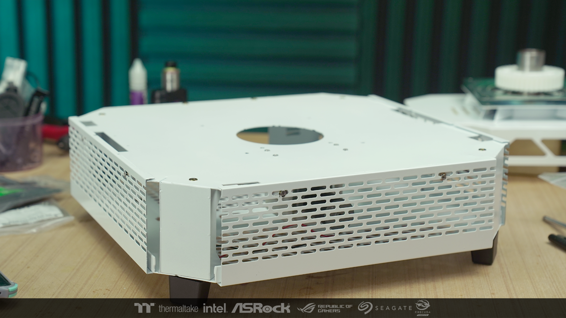
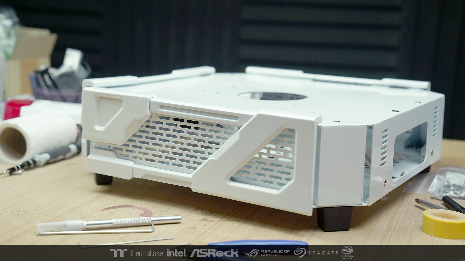
I moved to work in the base part. As I designed, I will slowly rotate parts of the hardware like a display standby. So I brought the motor to install.

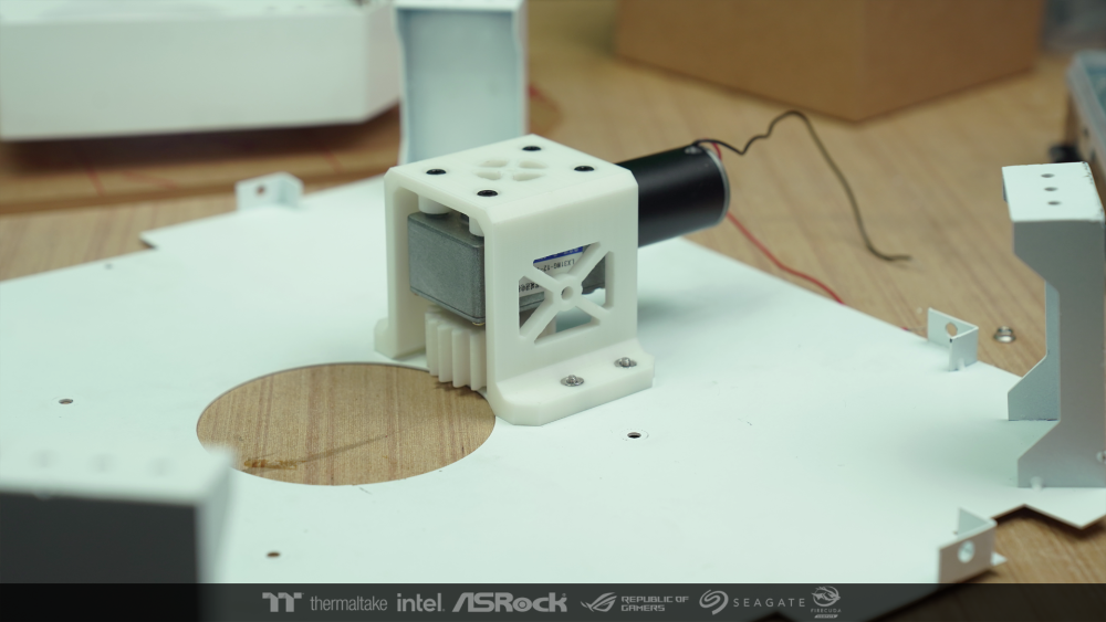
then bring the legs and the original wall to be installed

I tried to bring the created path to install. For check various screws that can be compatible.

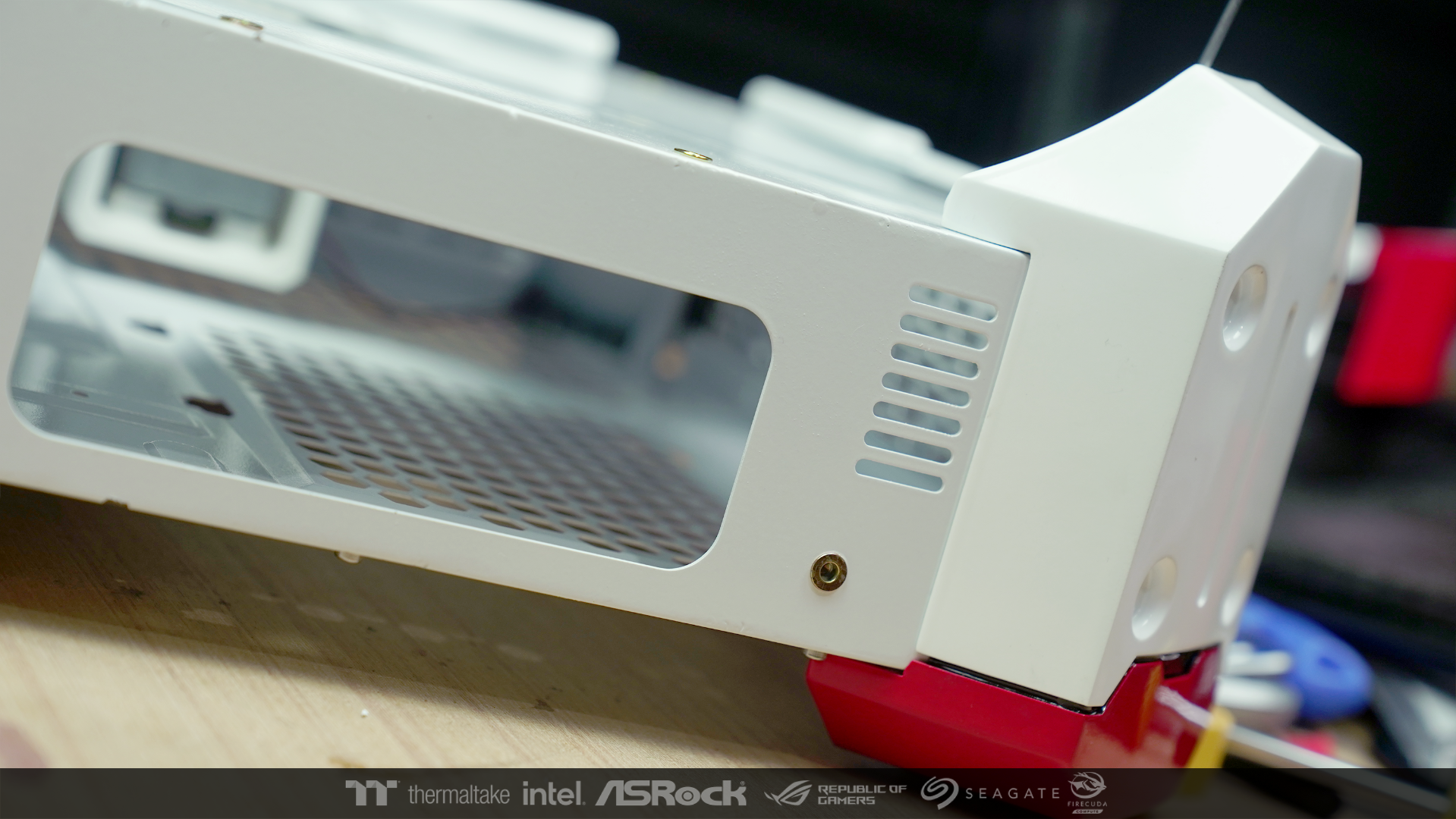
you cant't be able to see the bolt holes when the path was installed. because I designed some parts to overlapping.
The pieces that cover the bolt holes are mounted with strong magnets. It will be easy to lift and remove the wall when it needs maintenance.

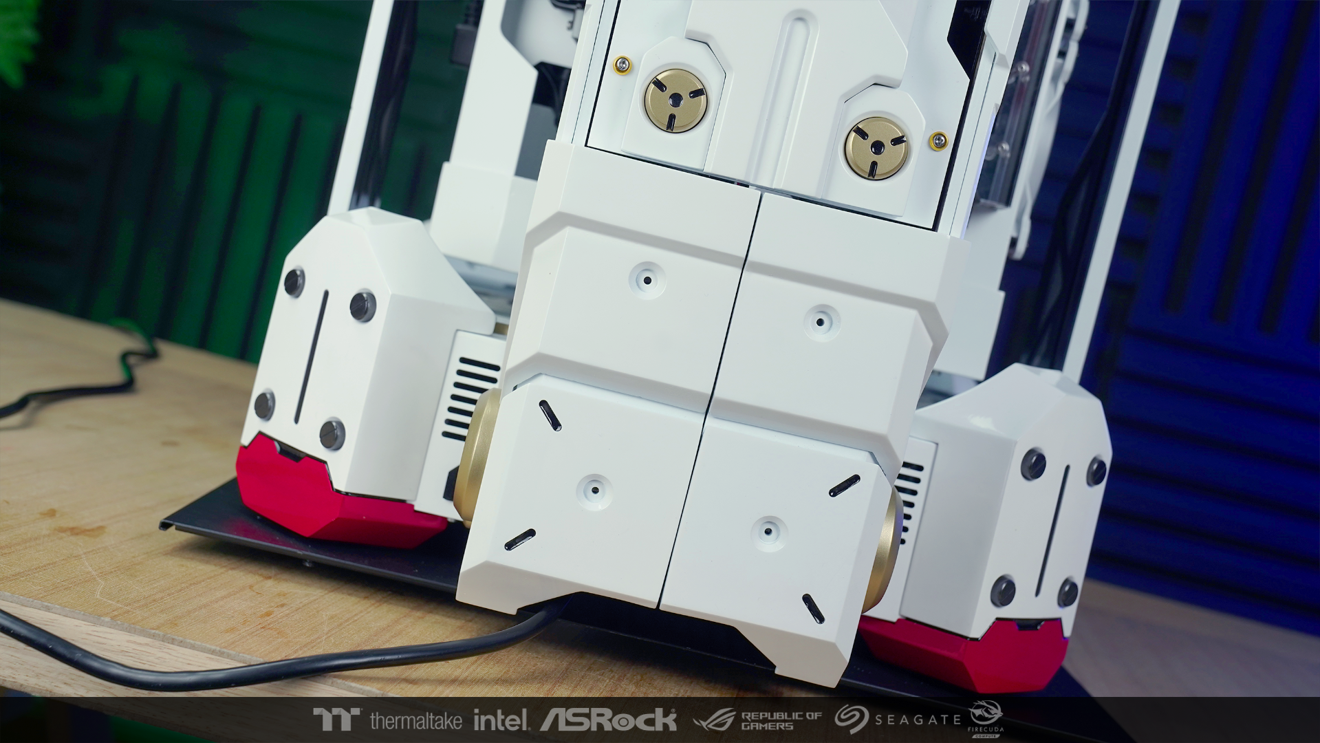
I put the main leg to check the joints of the part. that it will turn out to be correct.

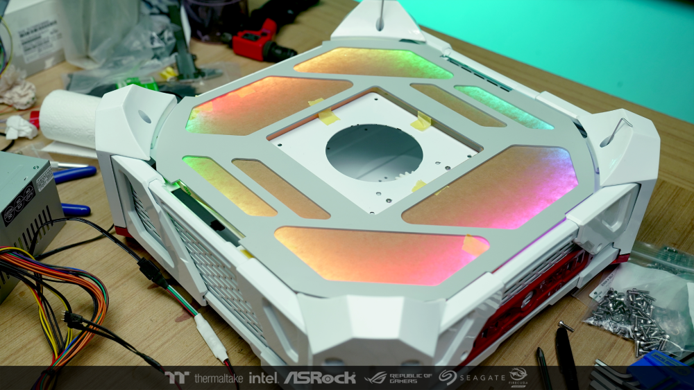
When everything was fine, When everything was fine, I put the box lights to check. it came out good 🤩
I want to work more. But I have to go to work in other provinces for 4 days. 😩
If I come back, I must hurry to finish this work in time. I hope everything is fine.
-
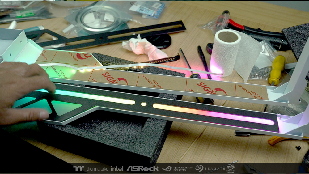
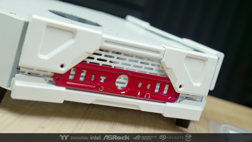
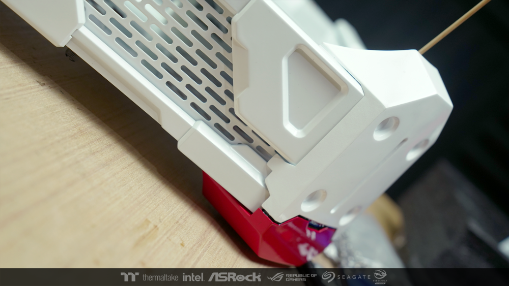
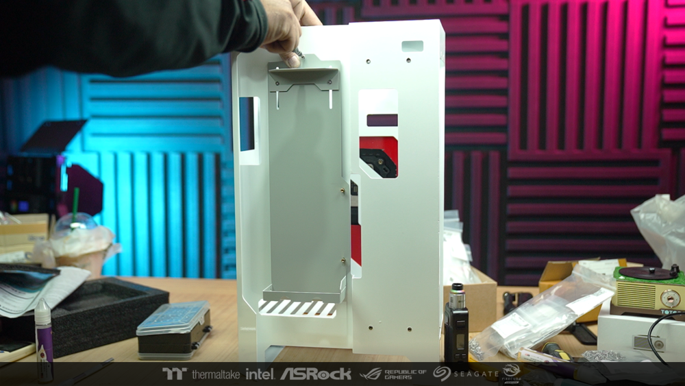
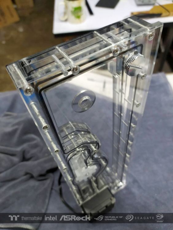
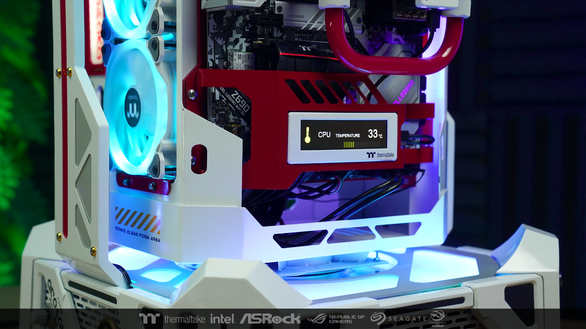
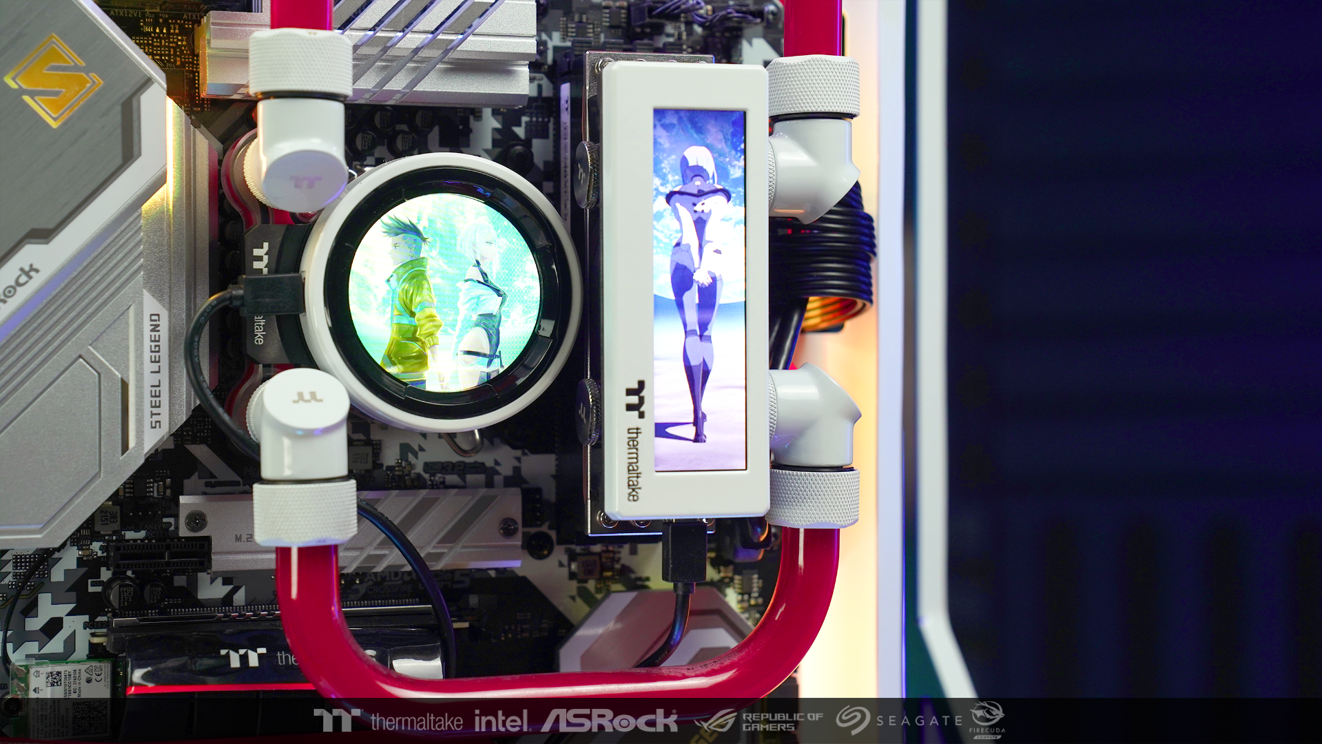
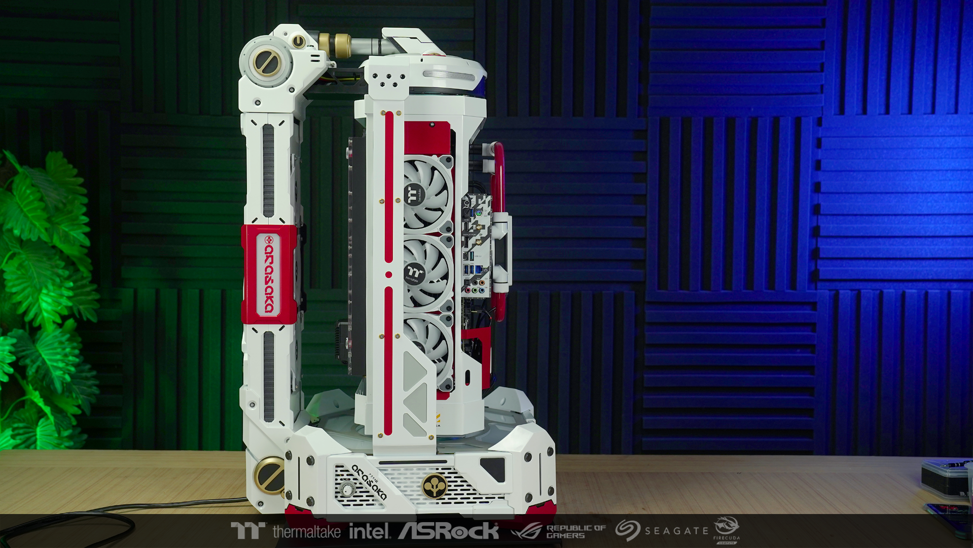
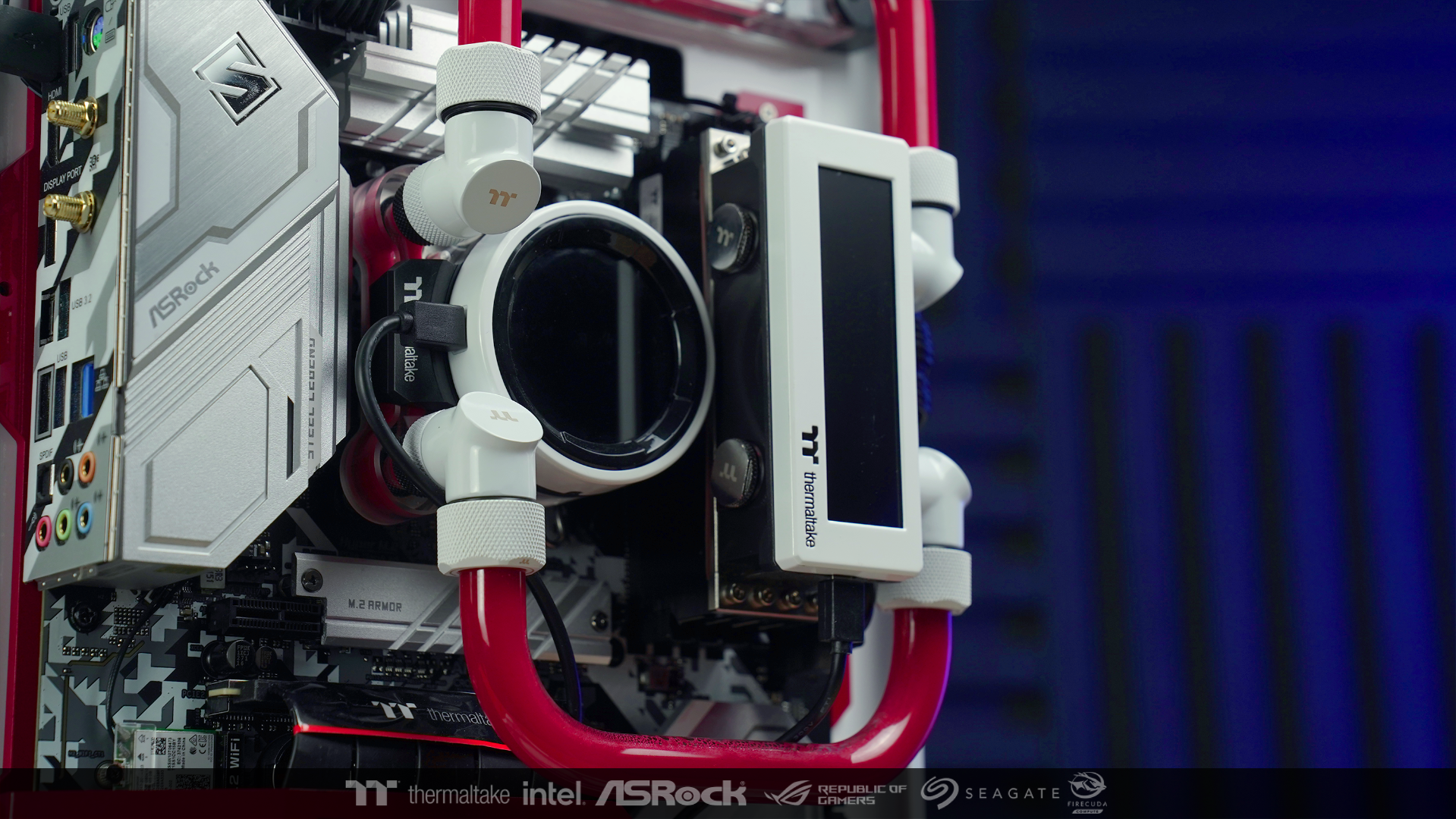
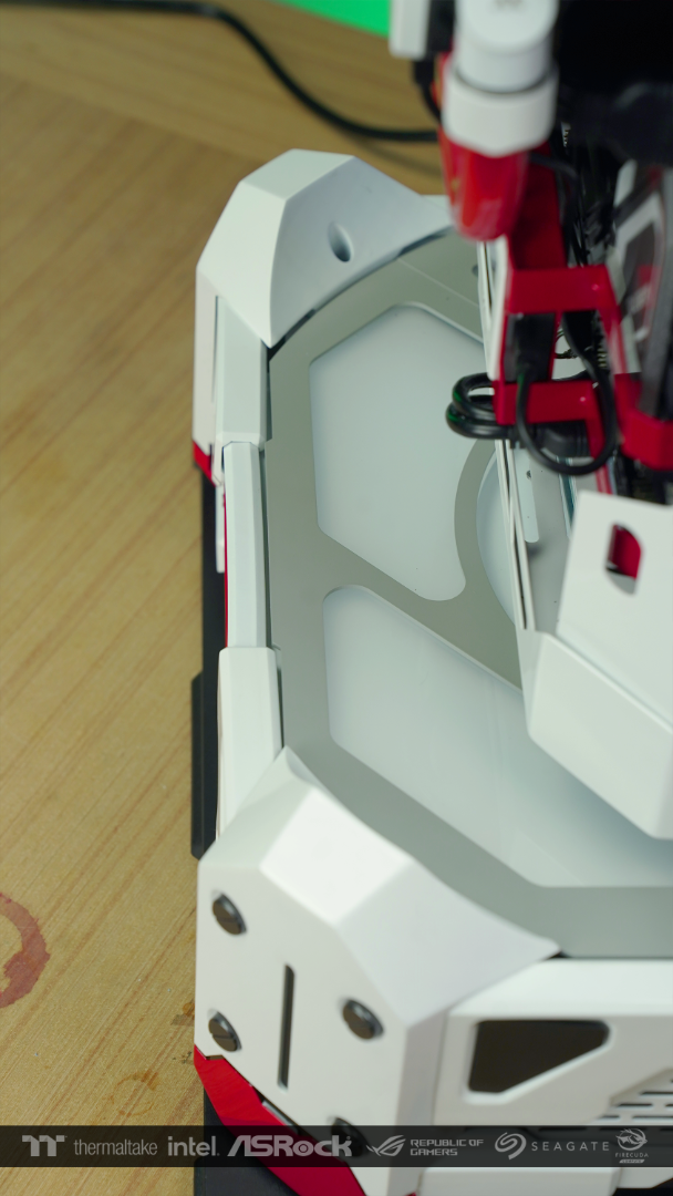
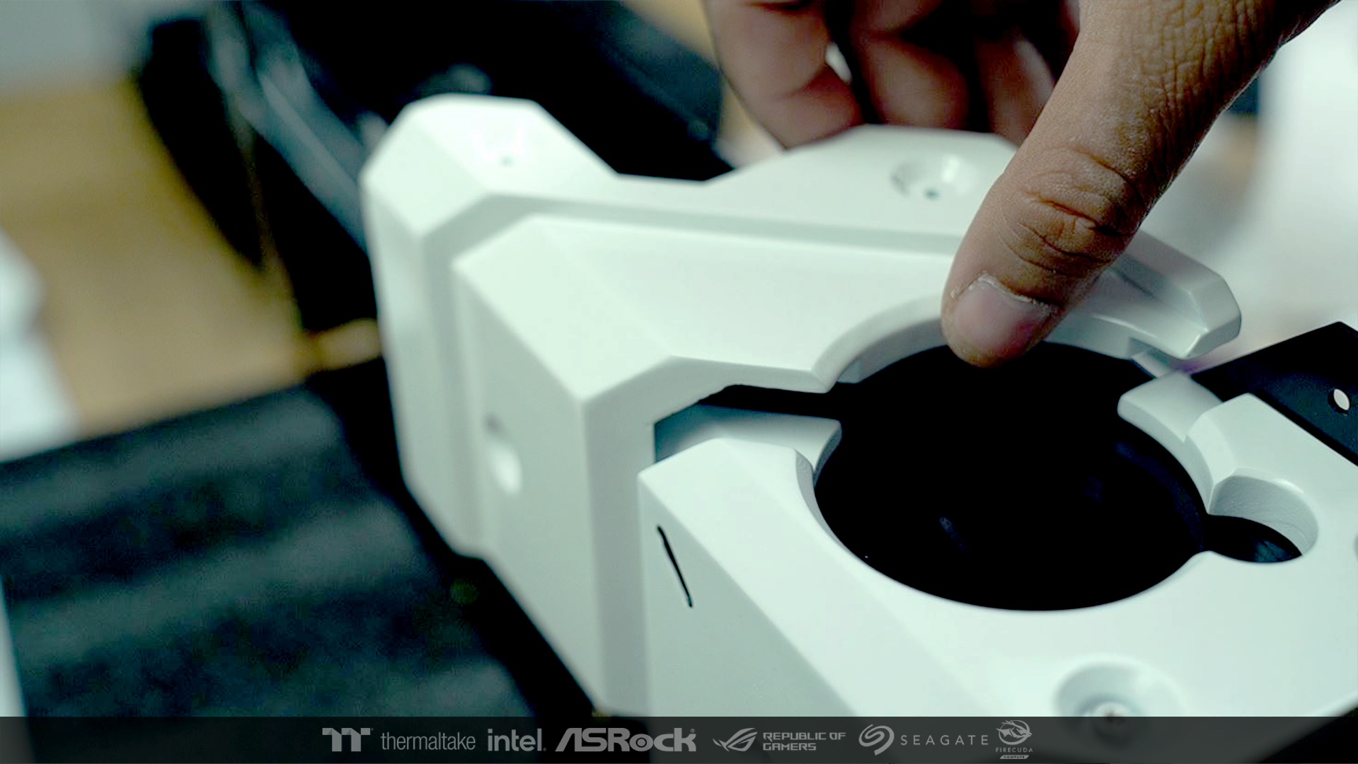
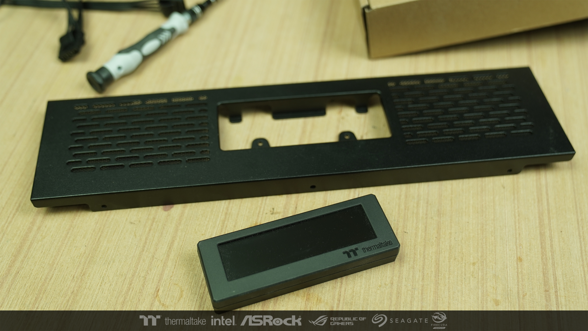
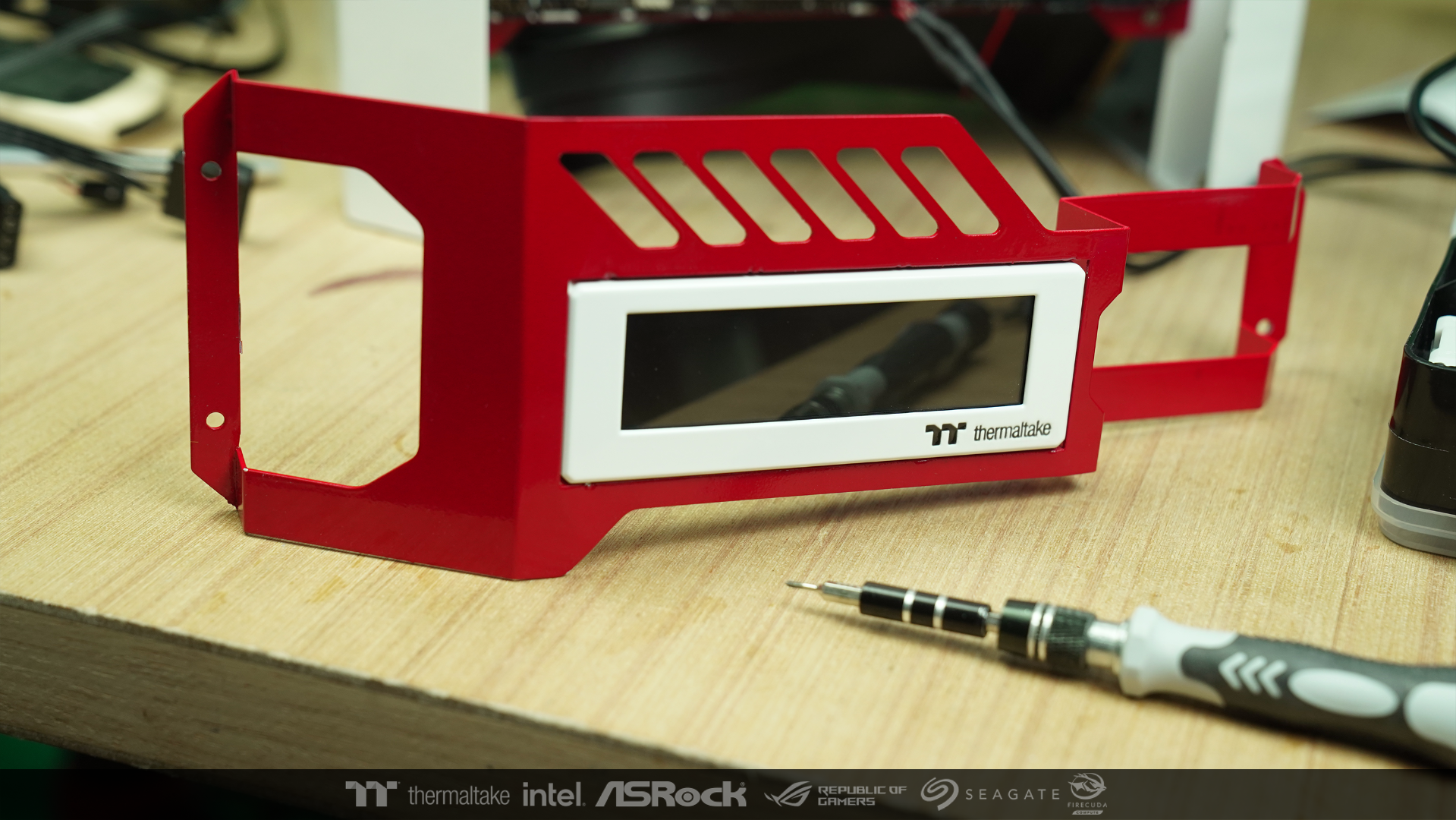
before moving to other parts I think it's better to do this side a little bit more.
This is the extension Monitor of the case that I received.
I took it apart and sprayed it along with the Monitor's frame of the water block

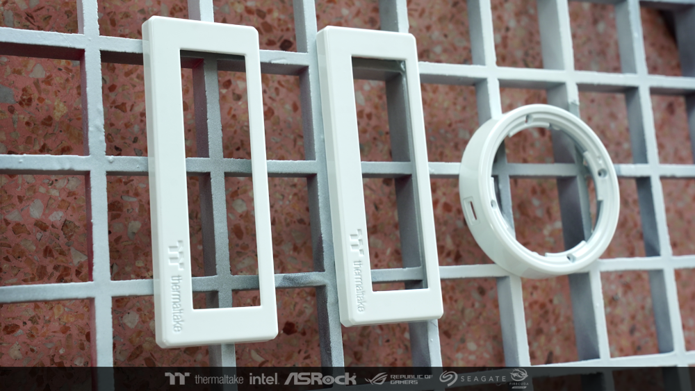
After that it was installed back and change the direction of the USB connector on the CPU block. It came out nice and good as I wanted.
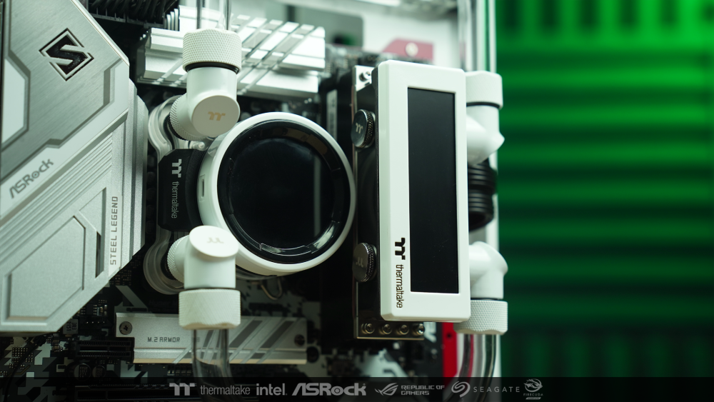
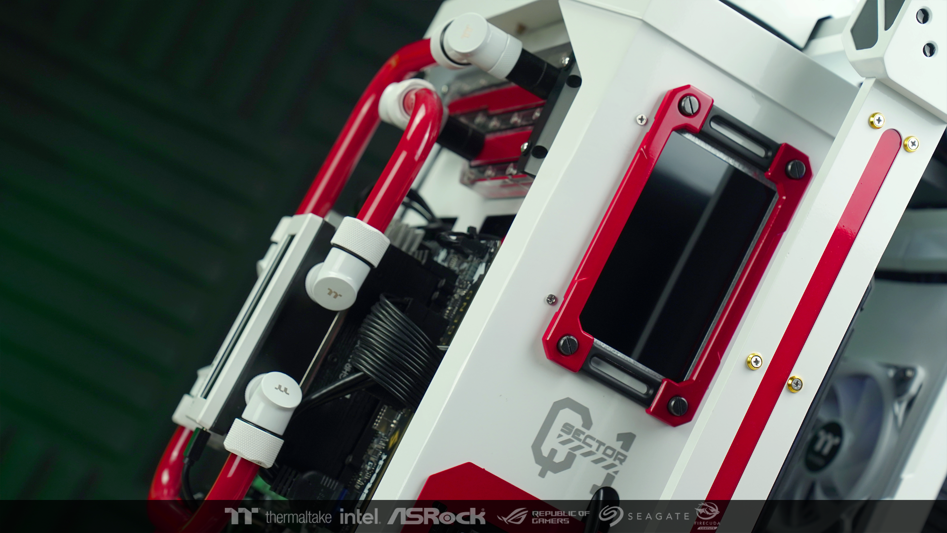
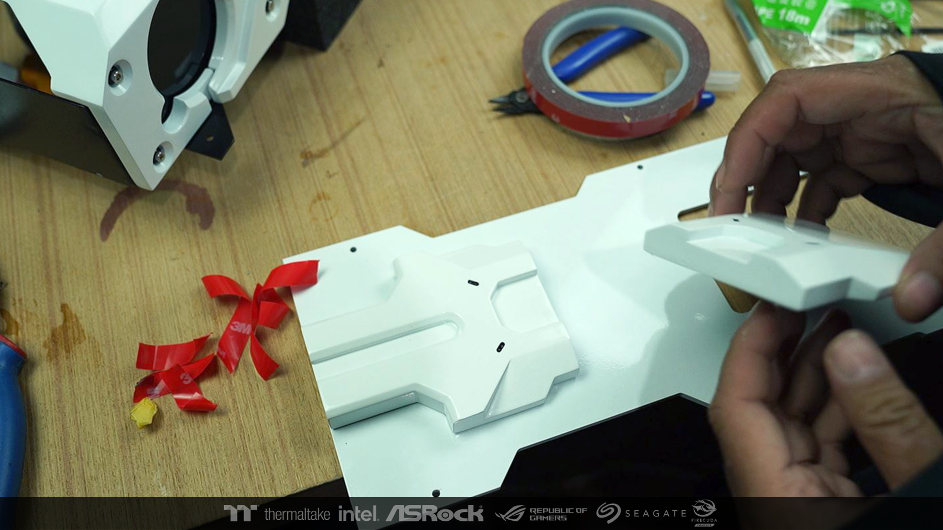
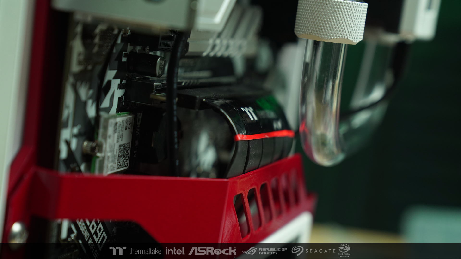
The screen that comes from the extension, I installed it at this part. I designed it to function like a belt.

I do this to tidy up the riser cable. And it also covers the connection points on the bottom of the motherboard. all for clean when looking


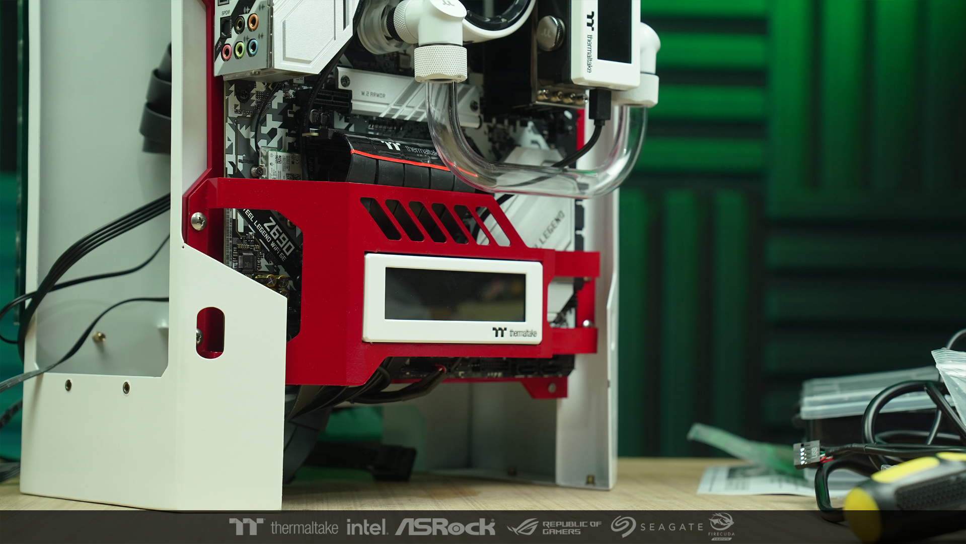
-
After that, I installed the monitor and PSU in the location that I designed
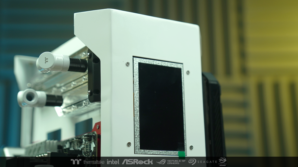
I think I will not finish it. Everything is just preparation. After installing fans on the radiator and bending tubes.
I will move on to assemble the other parts and then come back to finish the job.

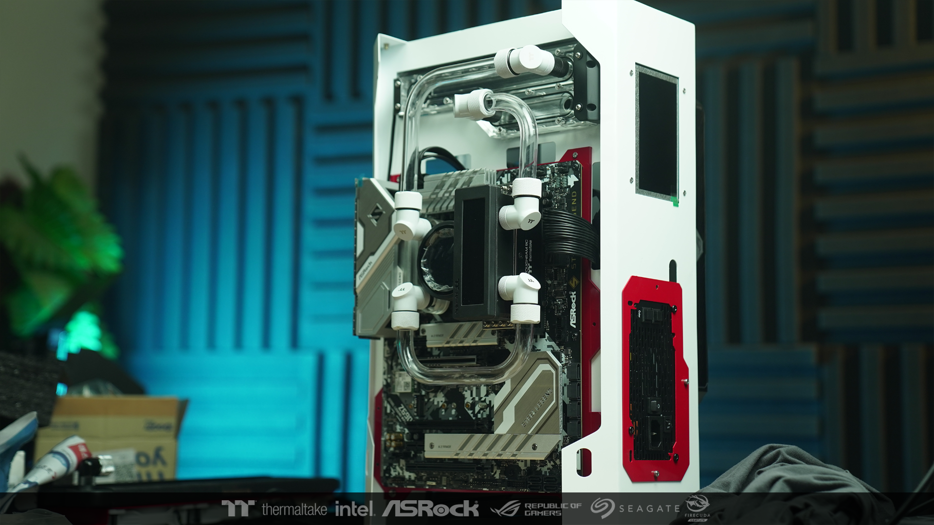
-
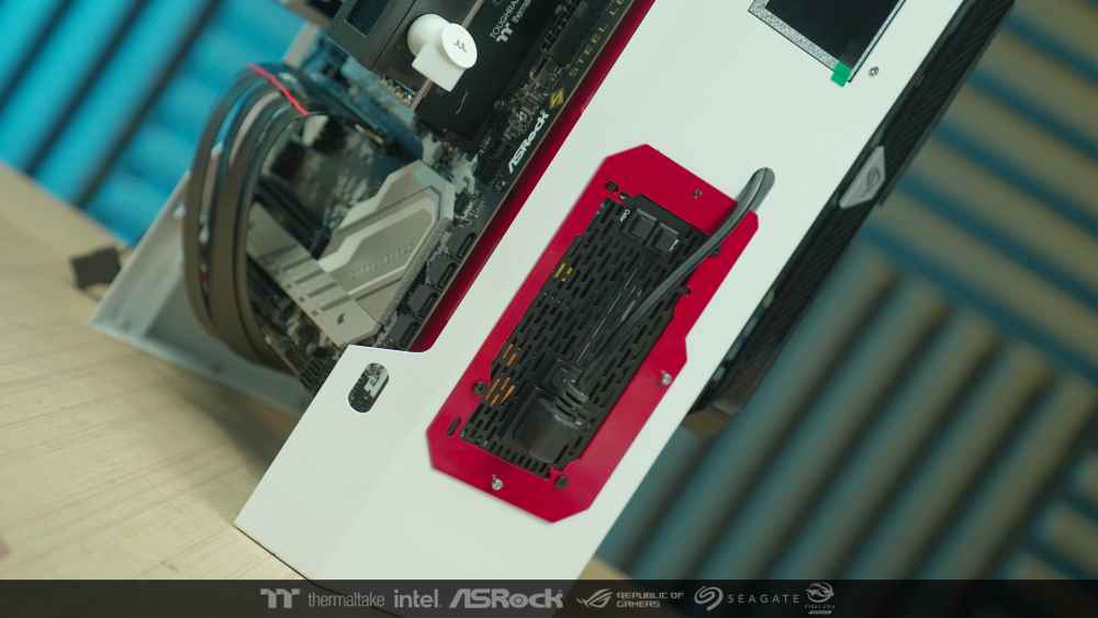
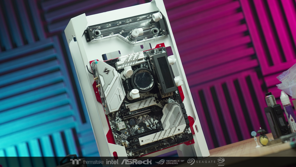
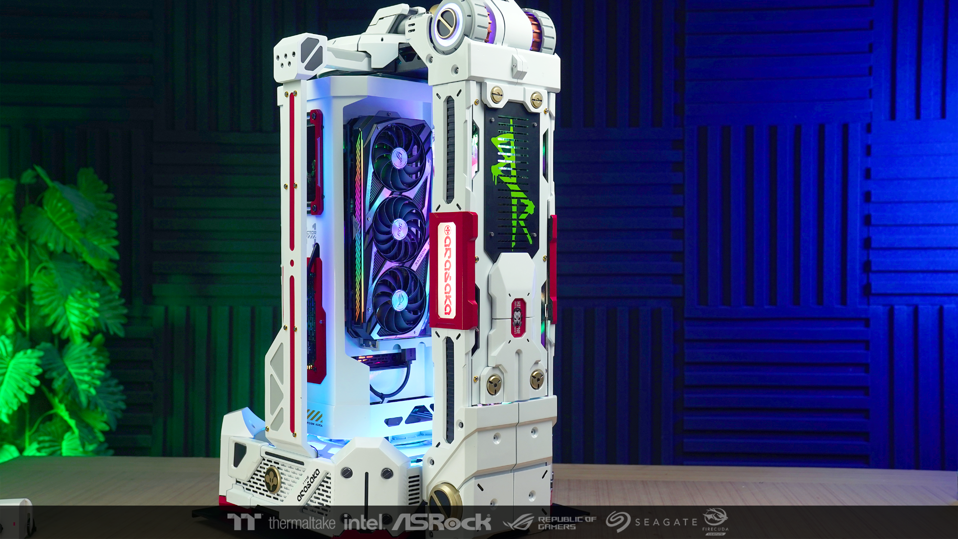
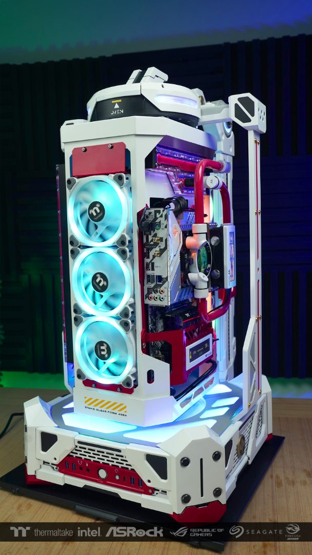
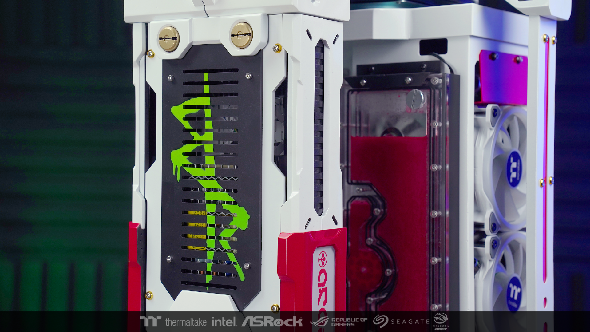
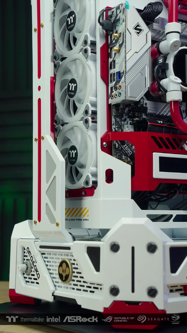
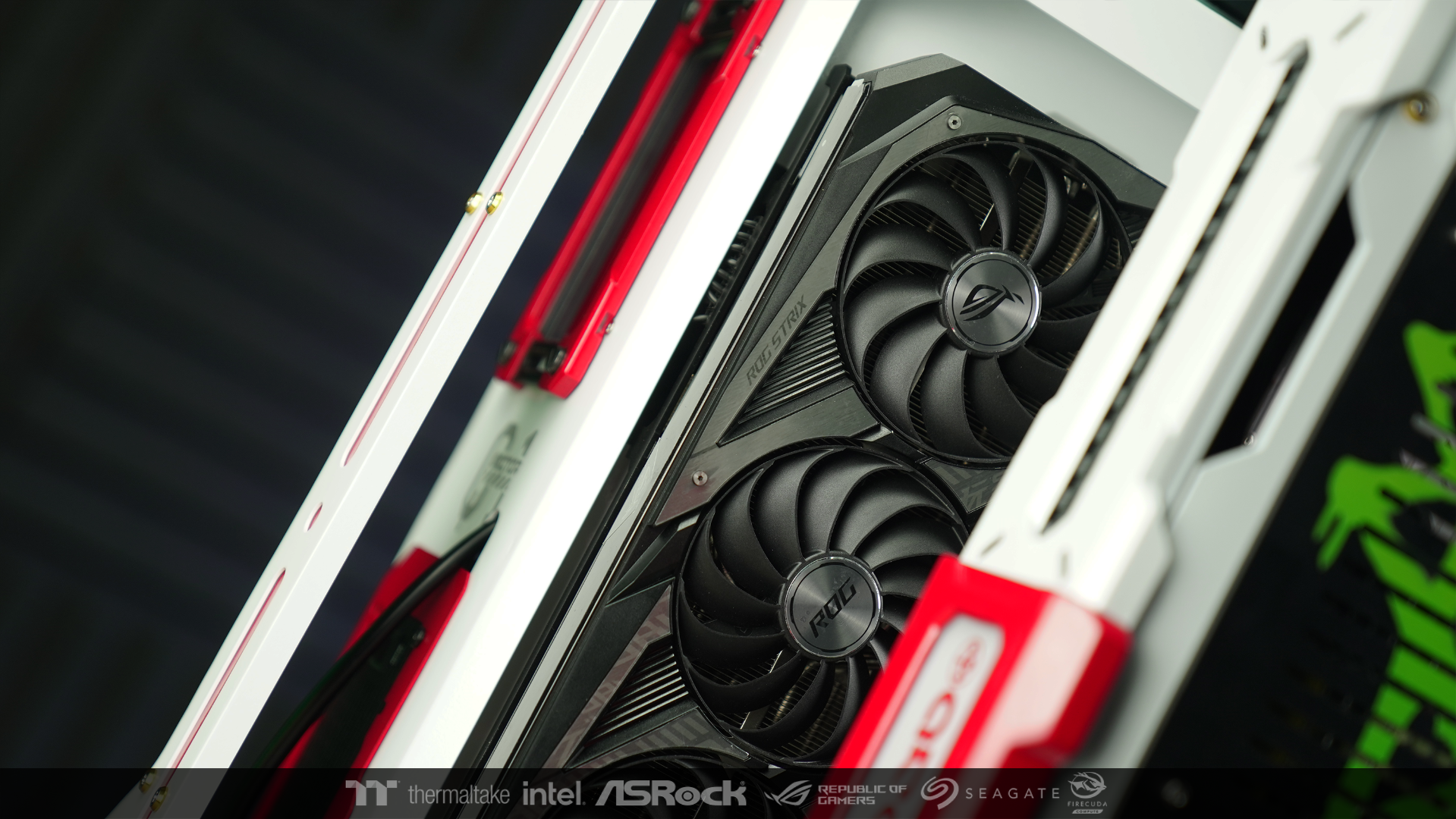
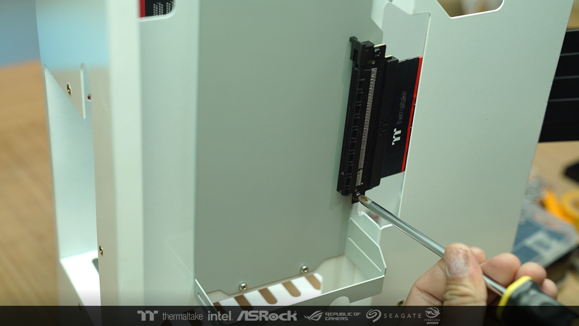
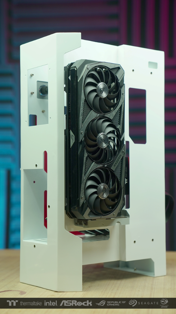
the other side opposite to the motherboard I installed a VGA, It will connect to the motherboard via riser cable PCI-E 4.0.
And this way I think the RGB light bar and ROG logo should make this side stand out.


And next to each other, the empty space will be the location of custom tank.

-
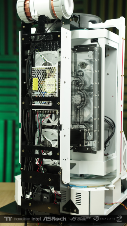
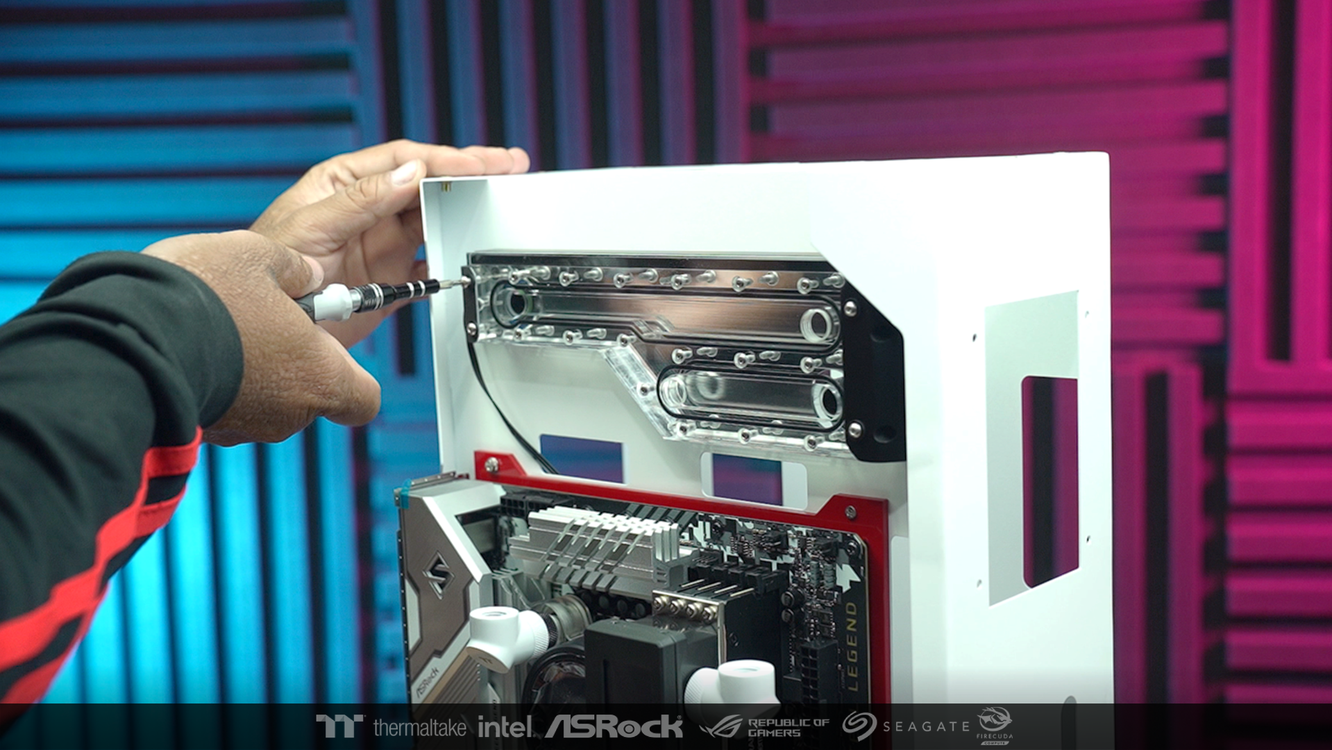
After that, I started assembling the hardware part. by starting to bring the rivet nut to install in the structure
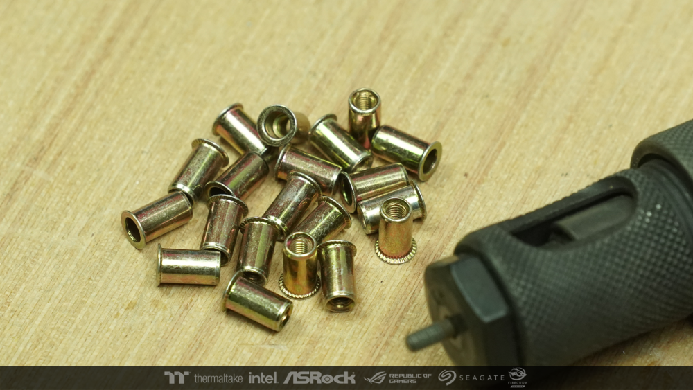
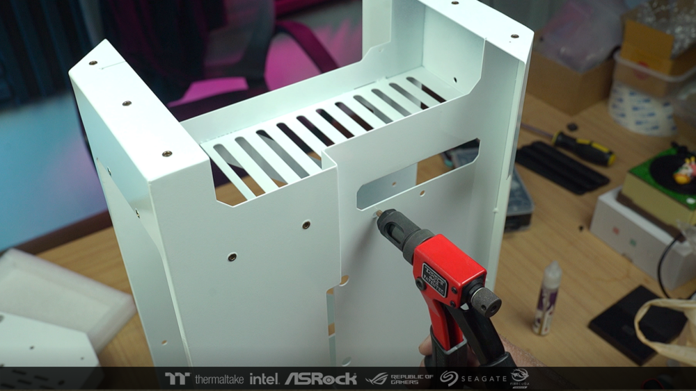
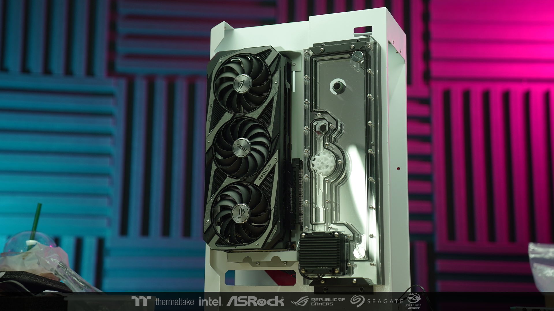
When the installation point is ready. So I put each piece of hardware together and then brought up and placed at the main structure.

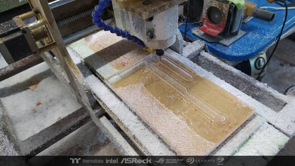
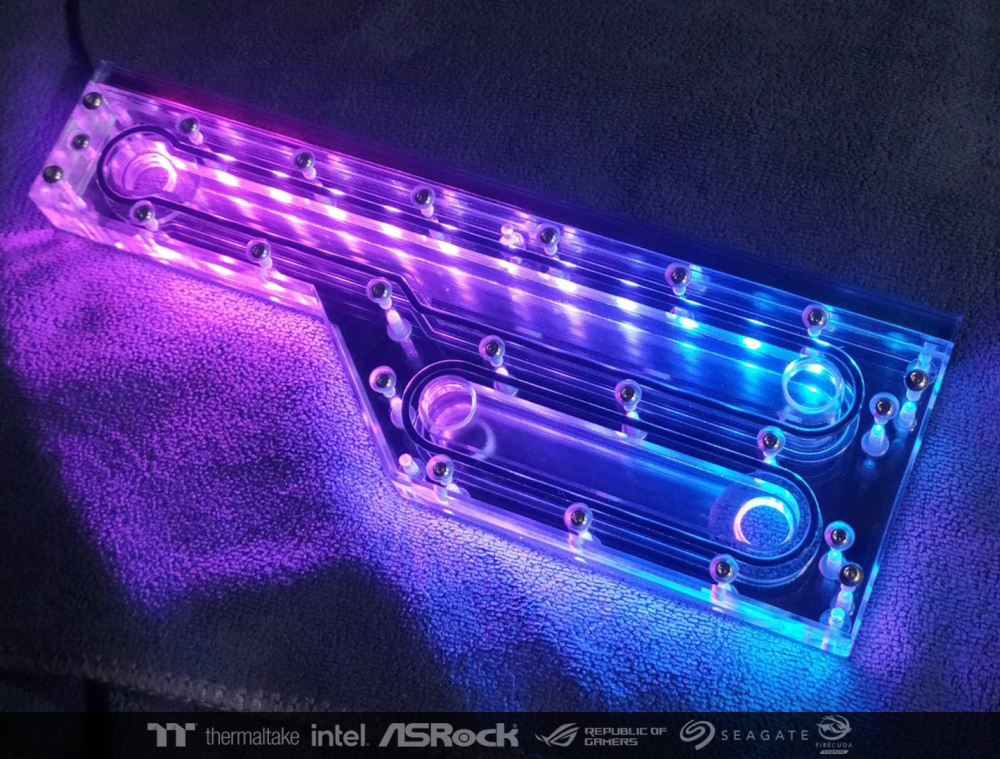
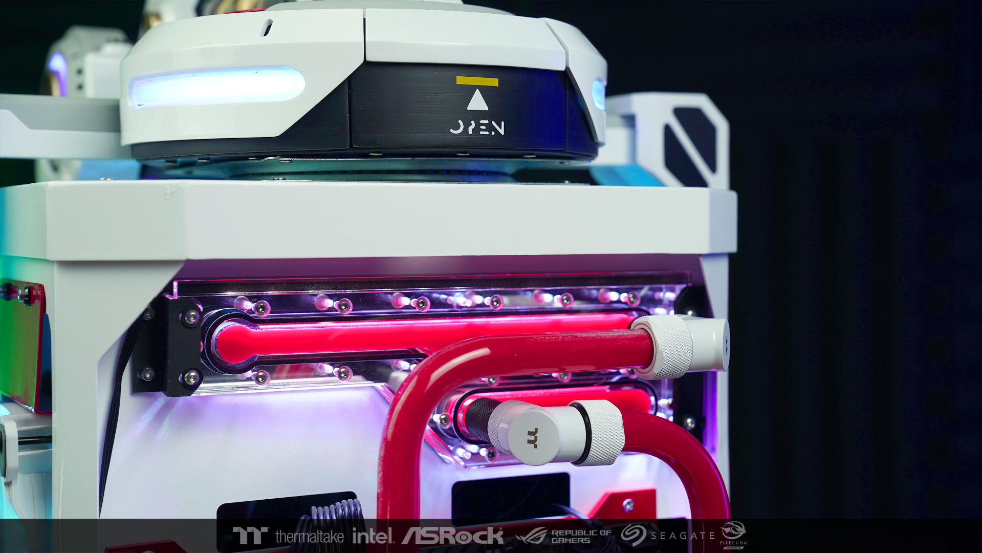
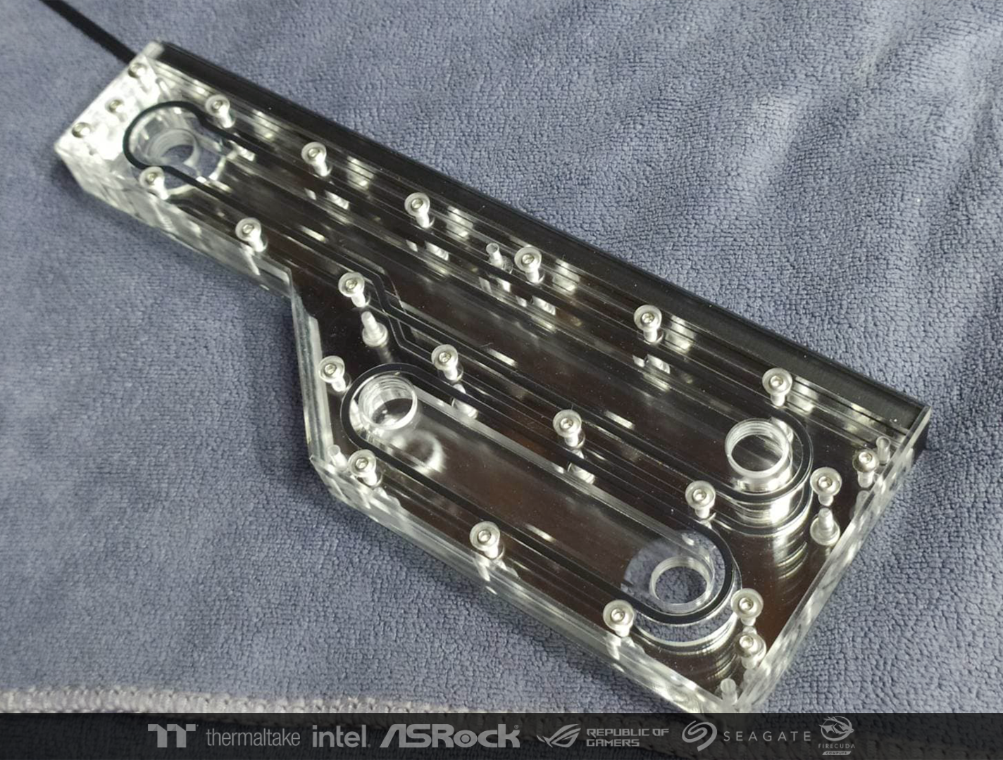
On this side, I made a Distro plate to connect the waterway with the other side.


The hardware installation point of this side, everything came out as I wanted.
-
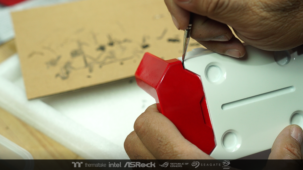
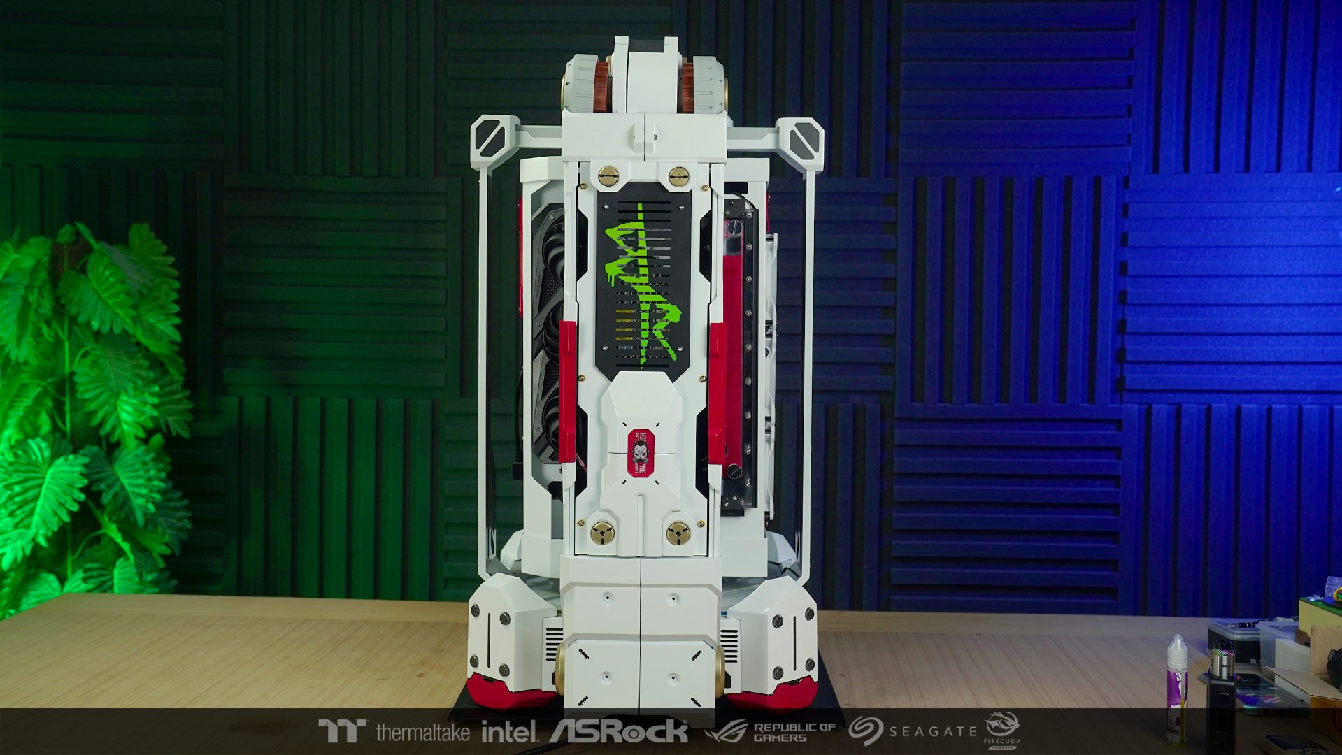
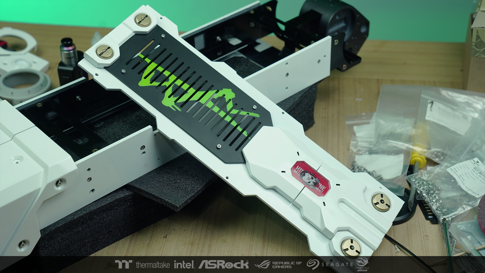
When the lacquer was finished, I added more details by applying black lines along the pattern I had drawn.

-
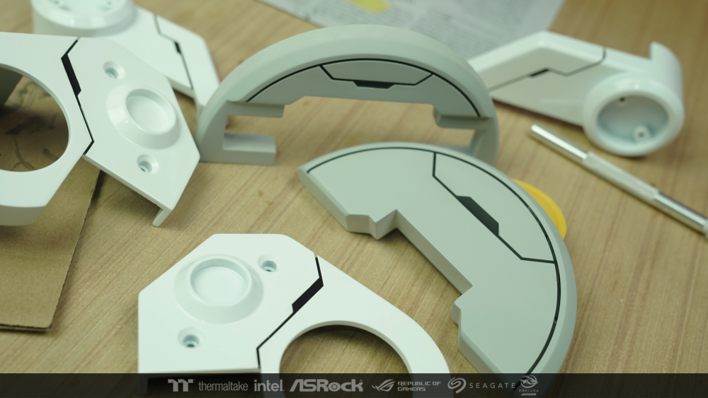
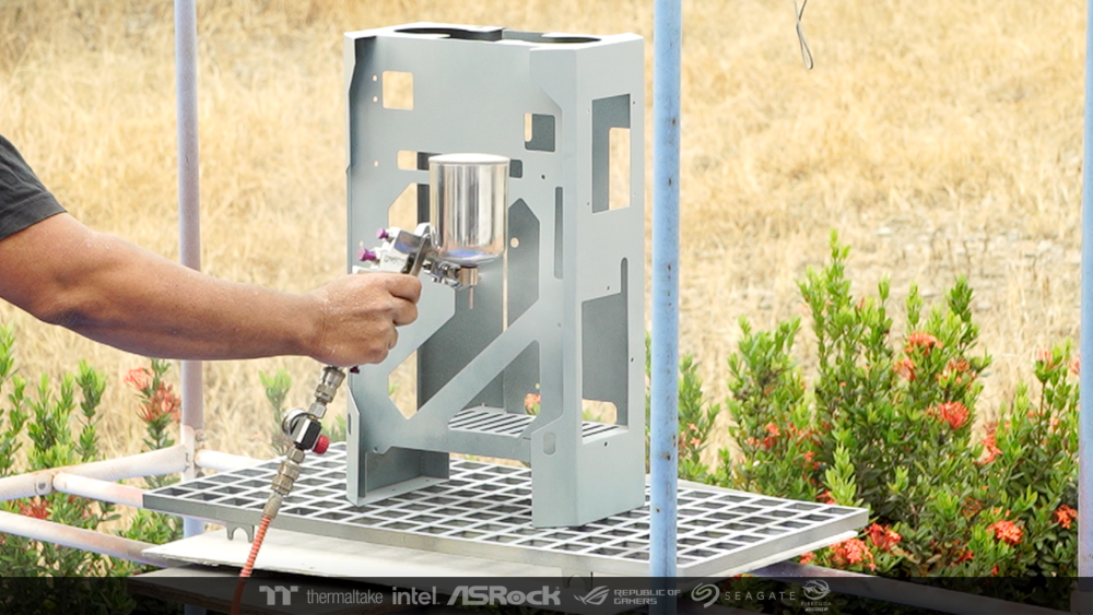
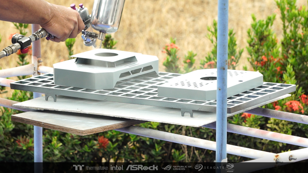
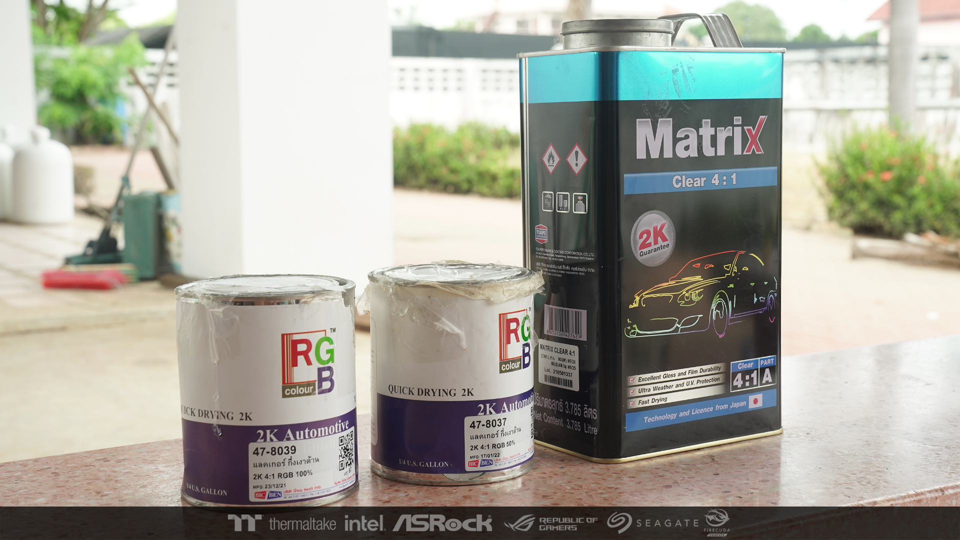
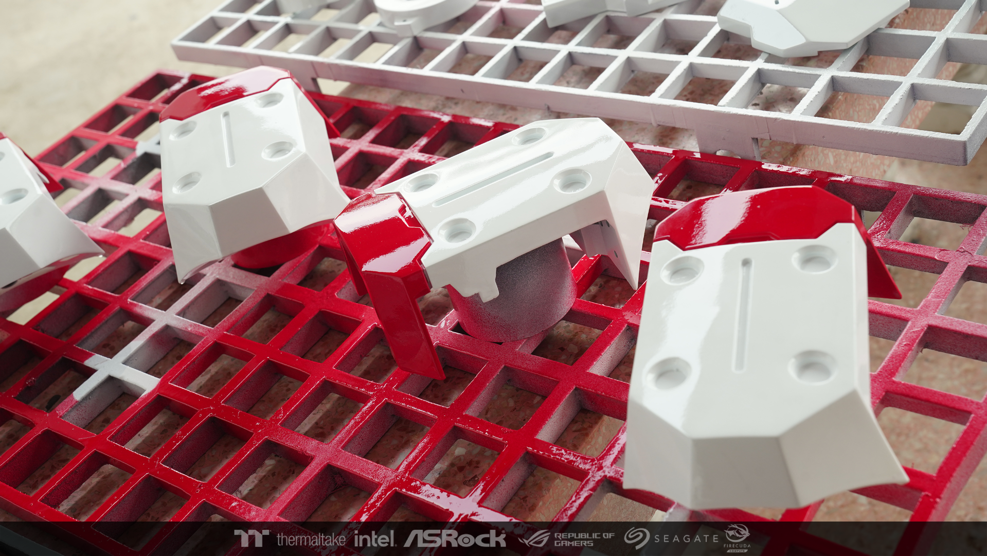
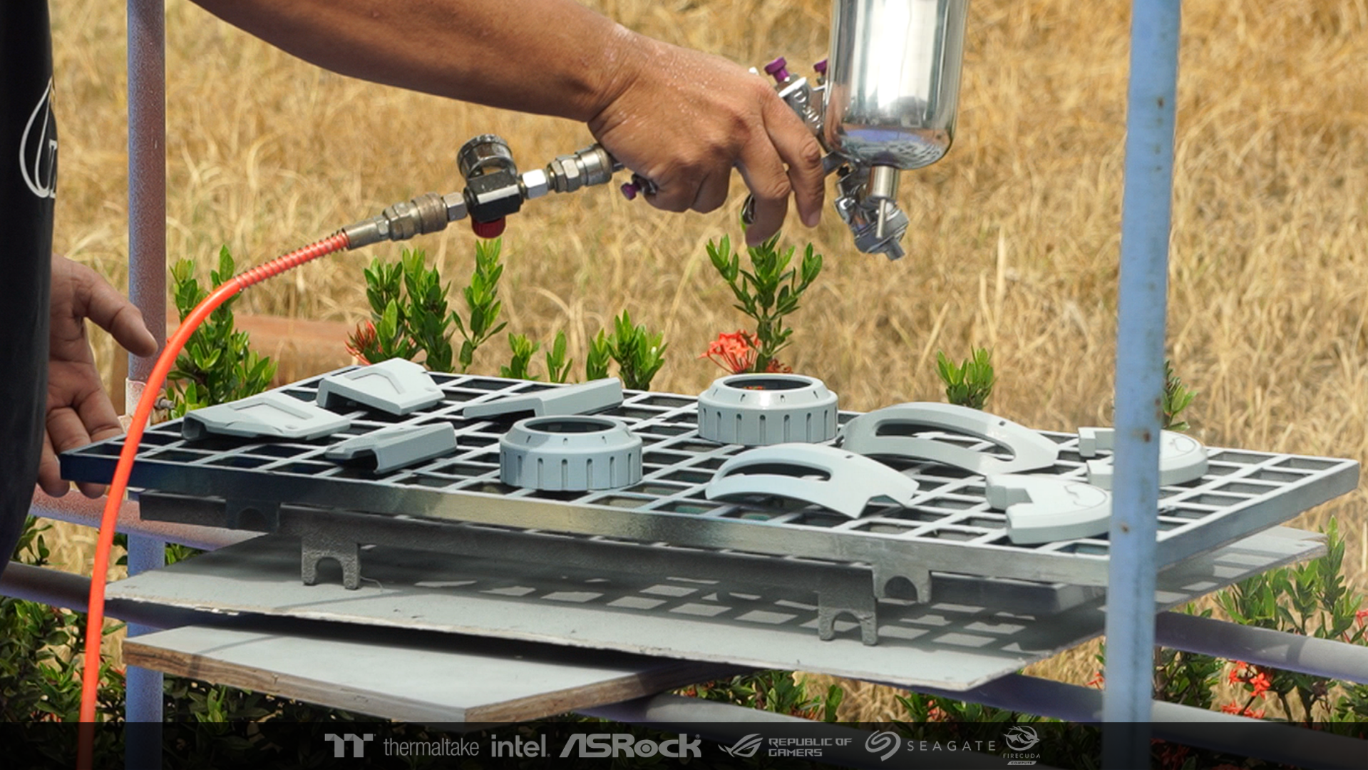
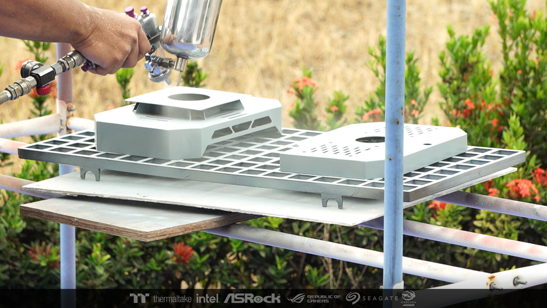
I was very reluctant to do shading or not at this job. Because usually I always use airbrush for shading in Sci-fi work. But this job is different. I imagined it as a new prototype. that just came out of the factory. So I choose to make the overall of the work come out as a brand new and luxurious work.
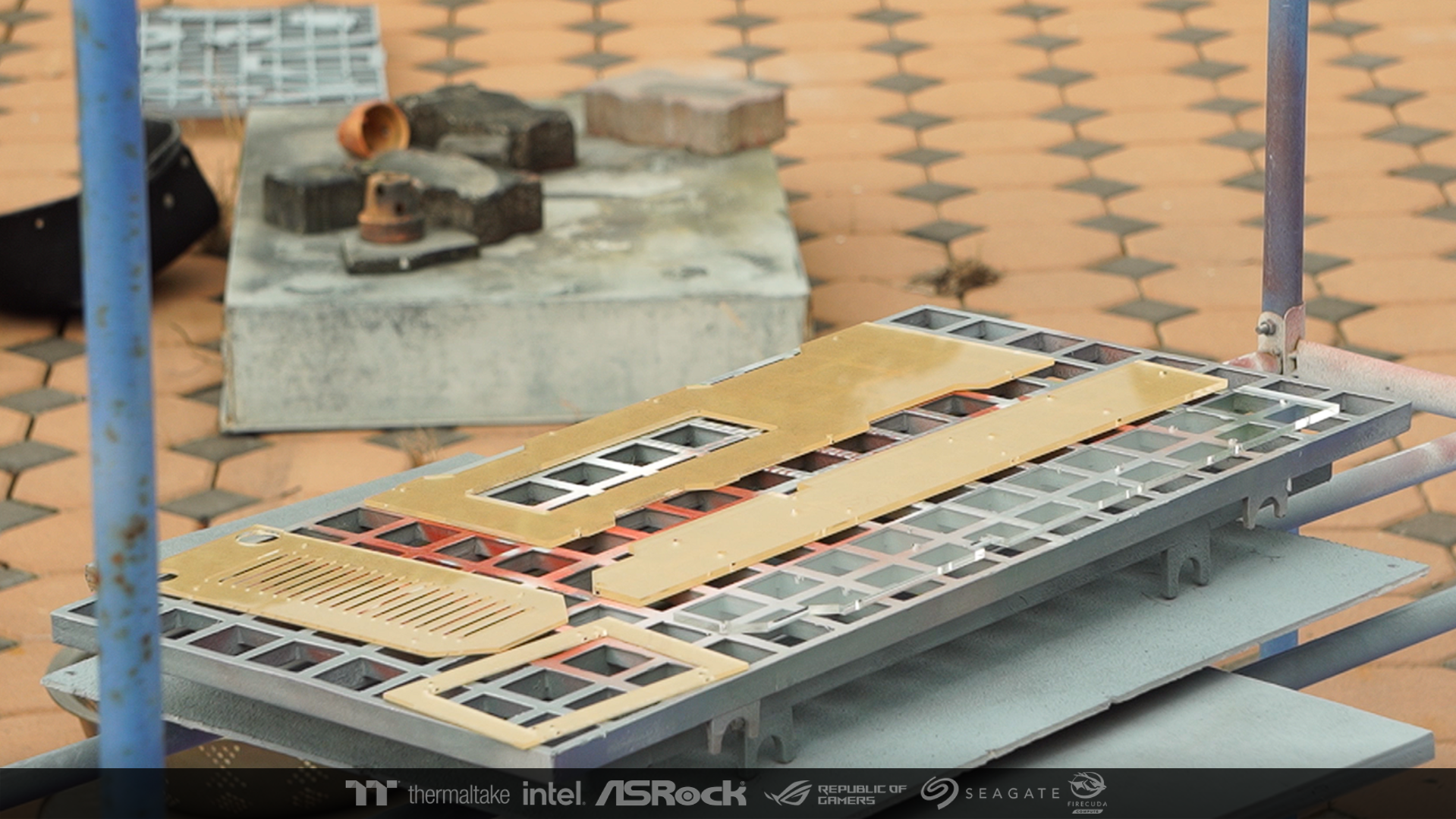
when i choose. So I brought the workpiece to spray lacquer. I used 3 types of lacquer to create additional texture differences in the work.

high glossy

Semi gloss
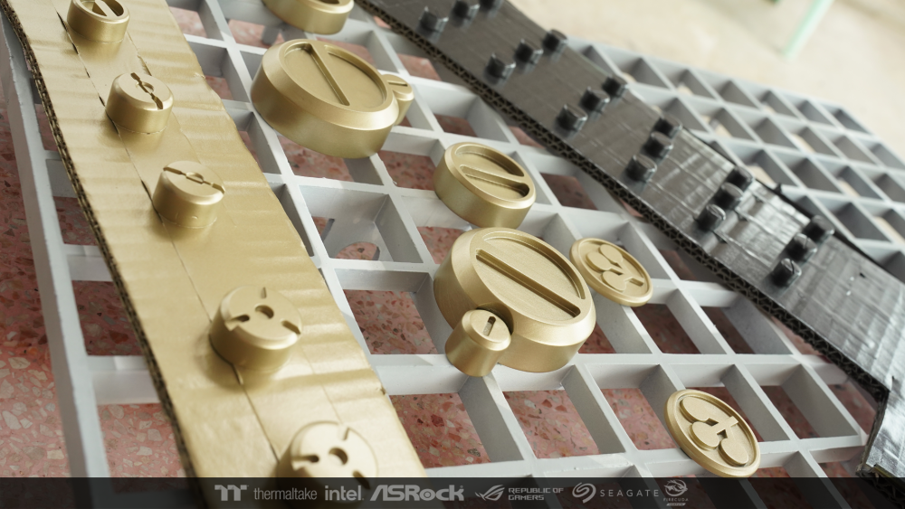
and matte color
-
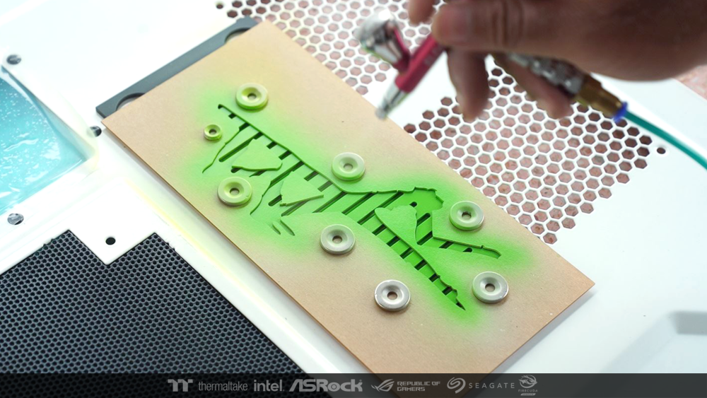
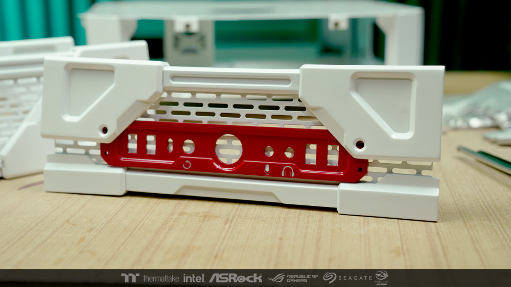
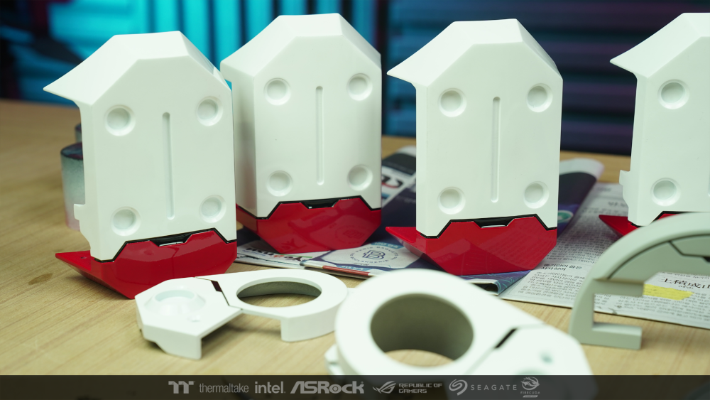
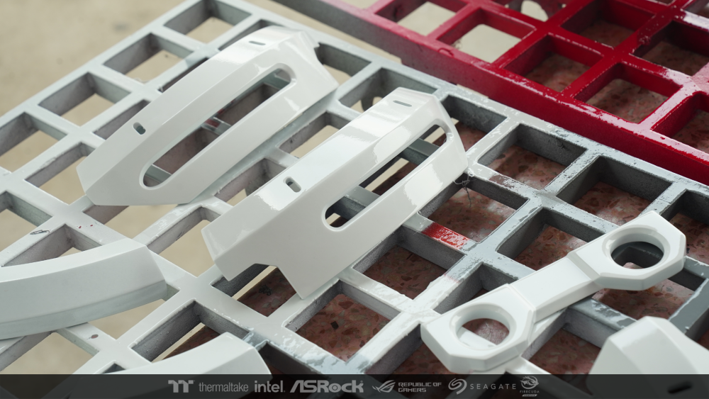
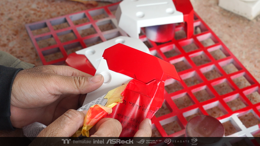
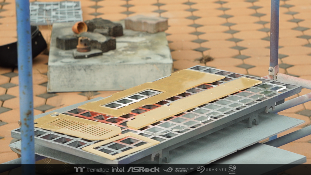
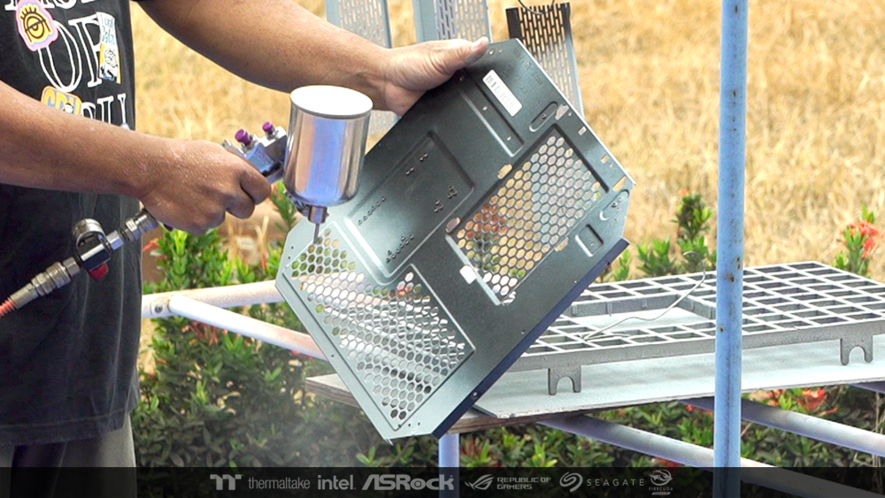
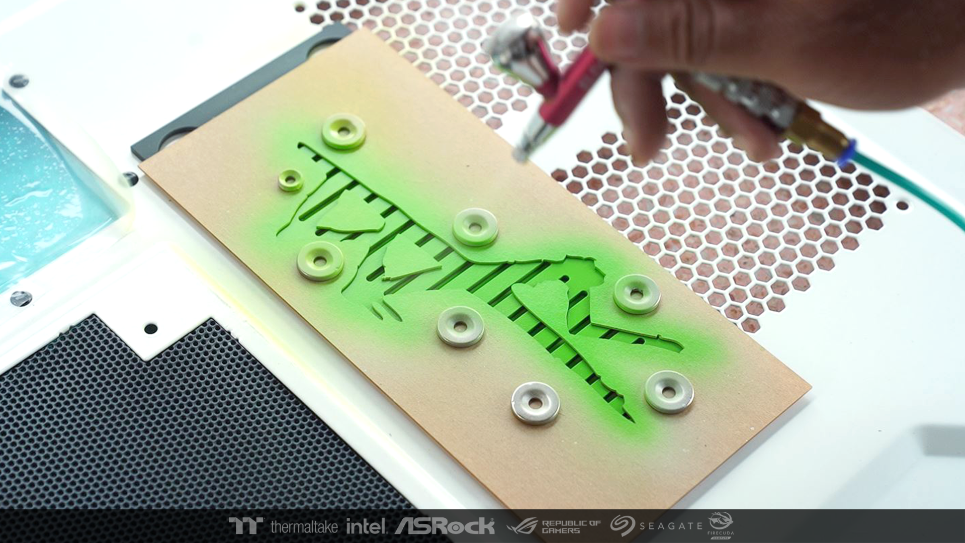
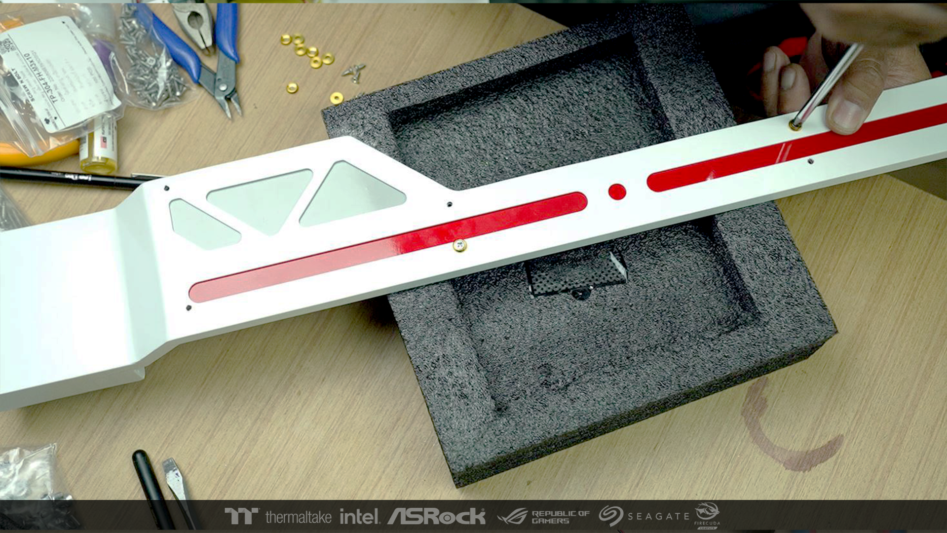
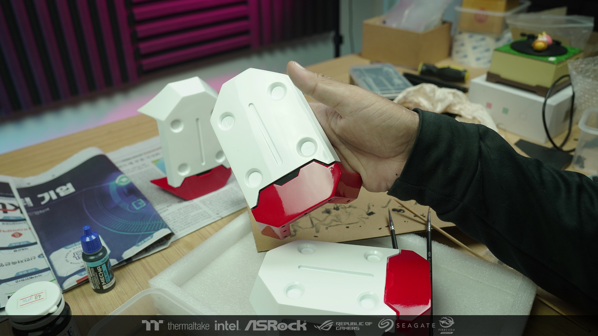
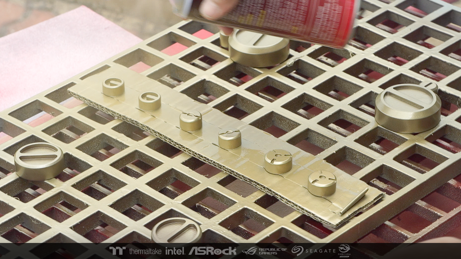
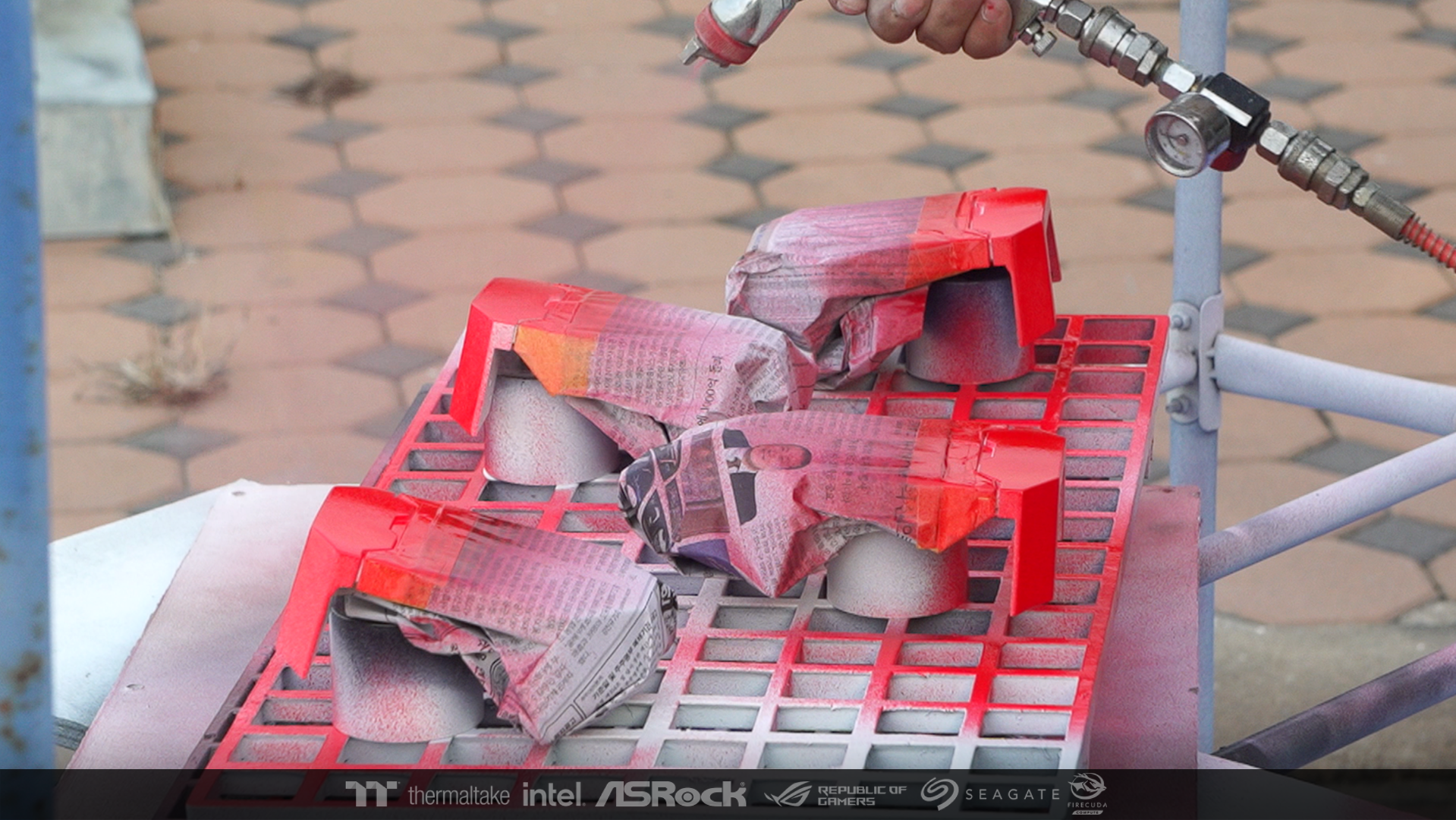
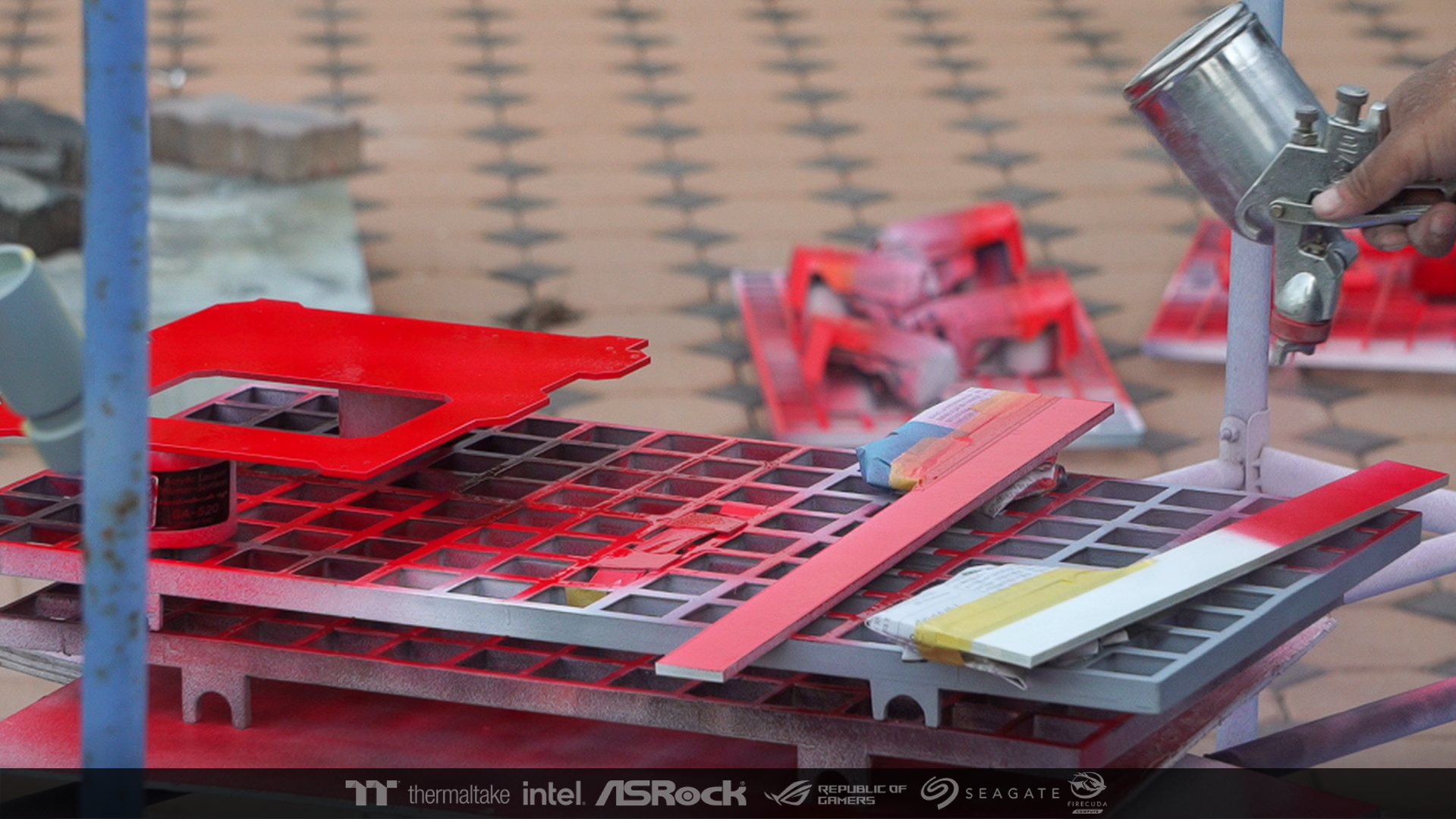
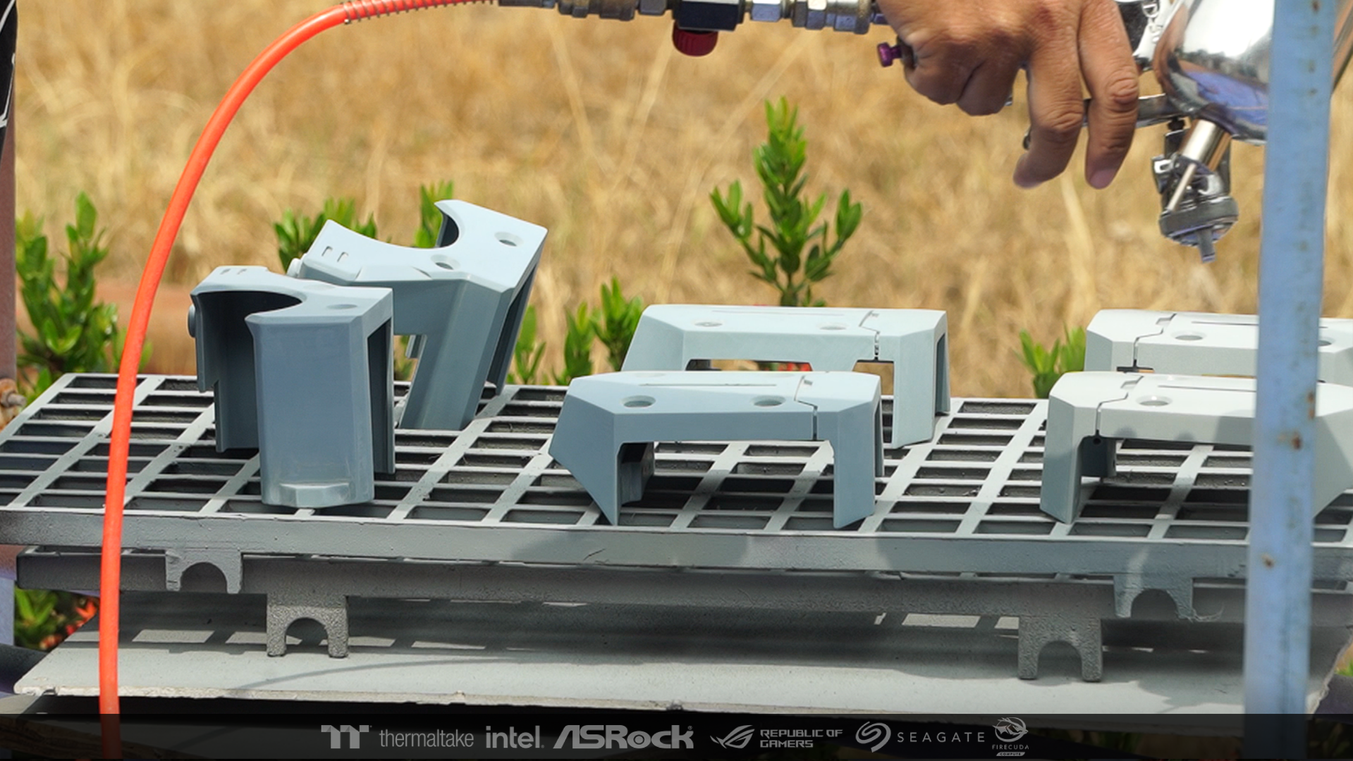
After the primer has been sprayed. I took every piece to spray paint according to the drawings.


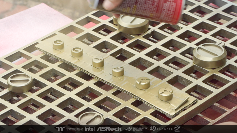
Some of them must be two-tone, white-red, I used Masking Tape and then sprayed.


-
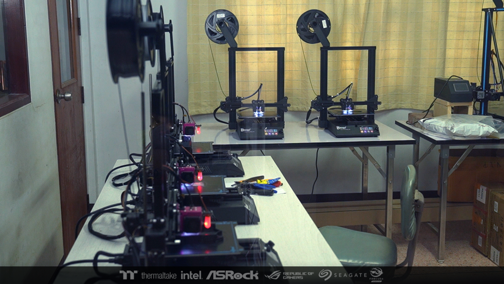
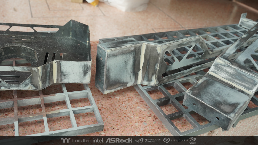
Once the design was complete, it took me another month to print it.
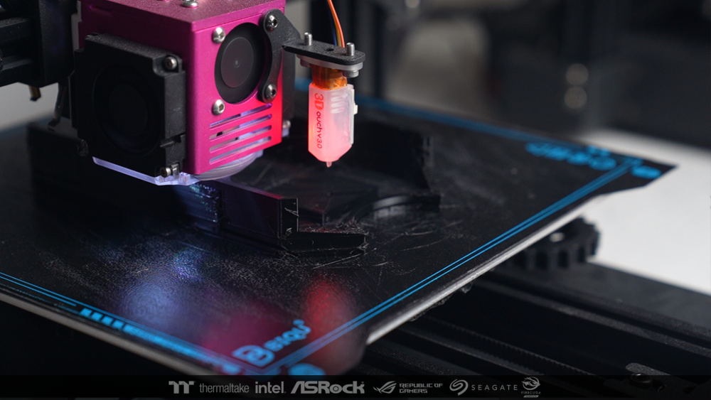
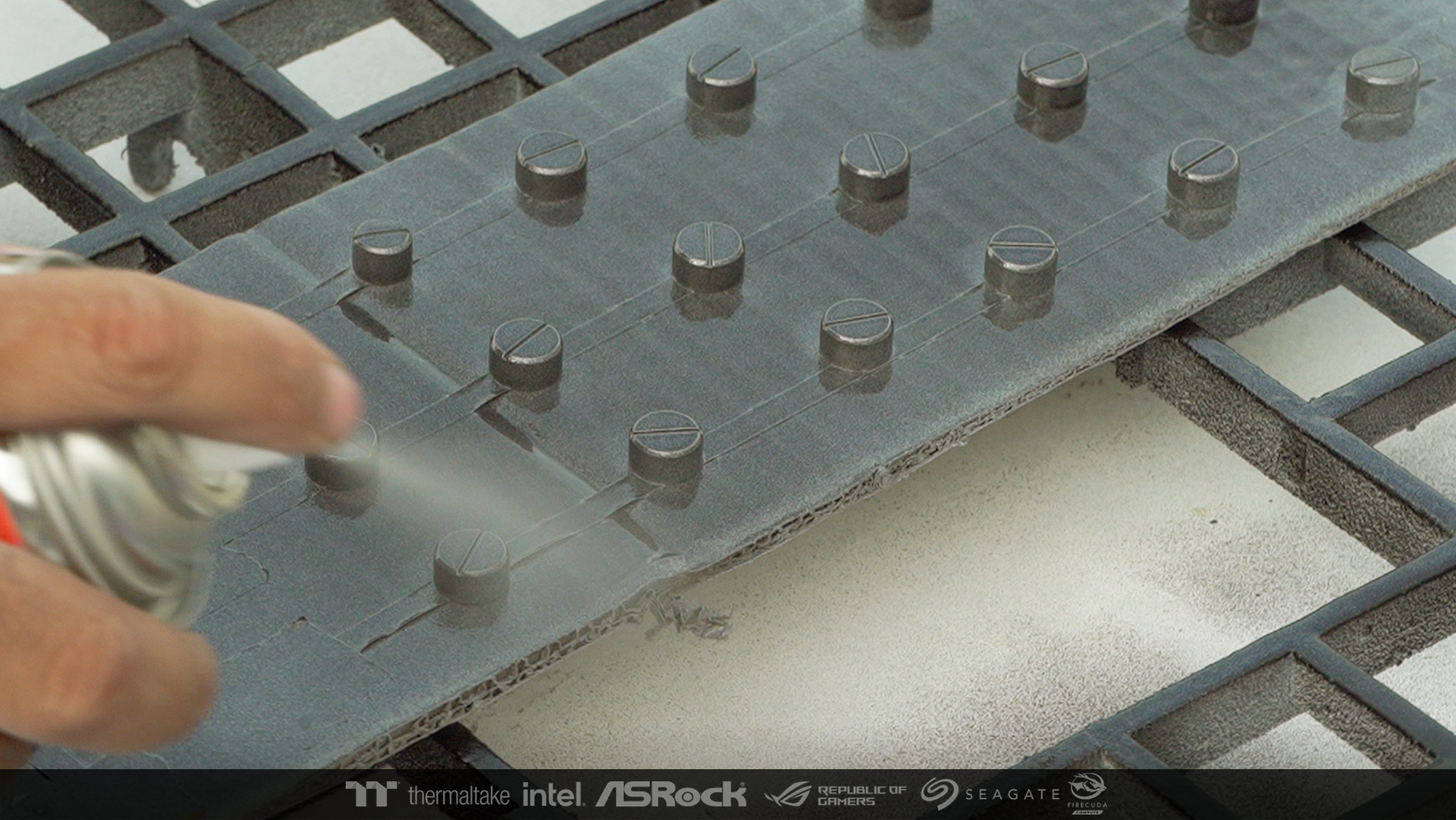
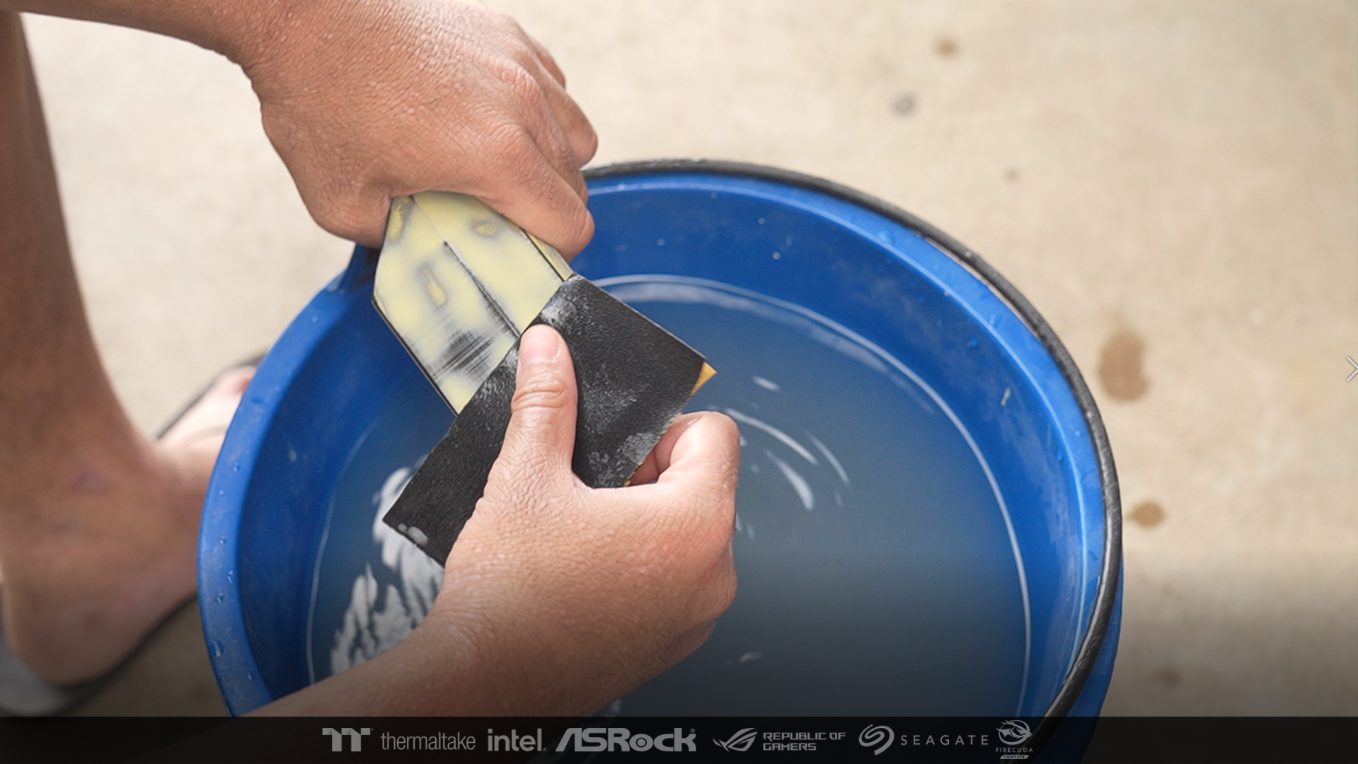
After that I used putty and sandpaper to polish them to a nice smooth surface. This process is very long. But I would like to take just one photo. because during job ,my hands are so messed up that I don't want to touch the camera or mobile phone.
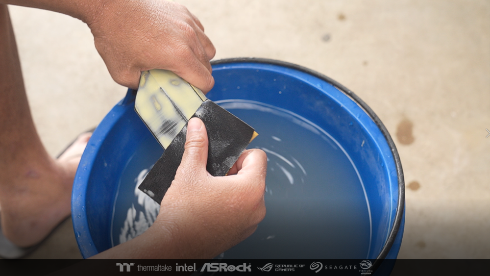
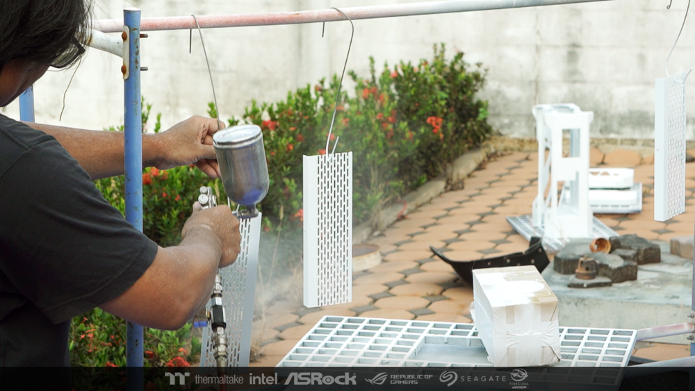
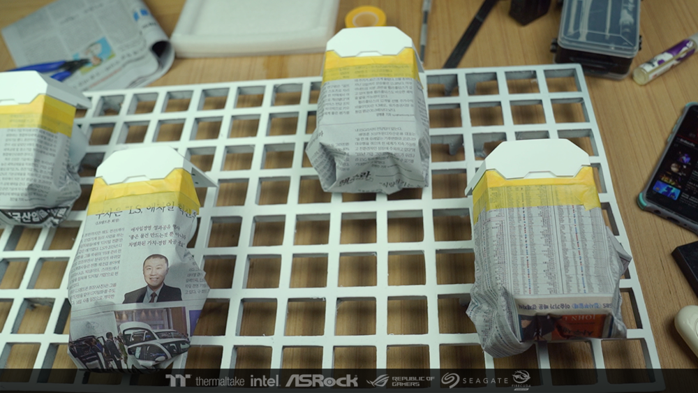
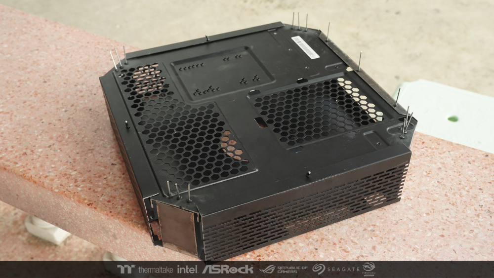
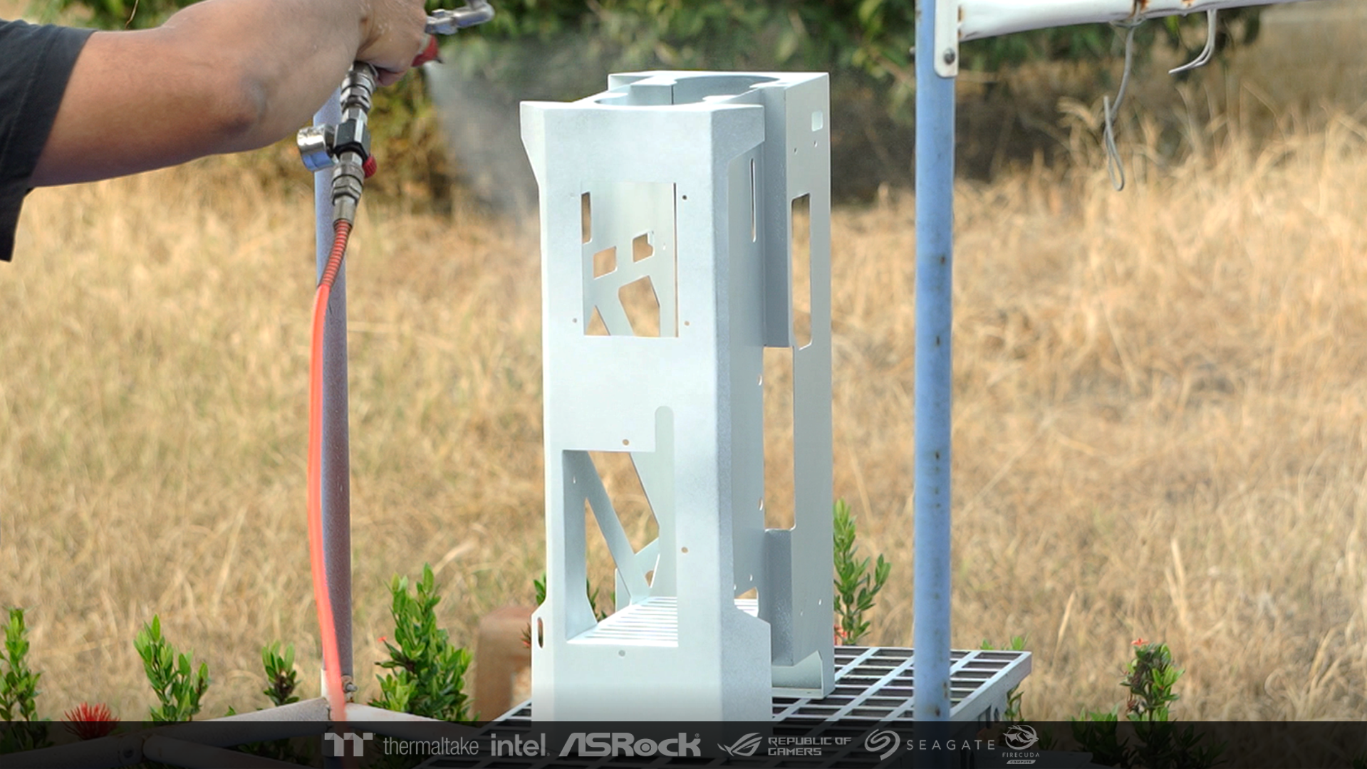
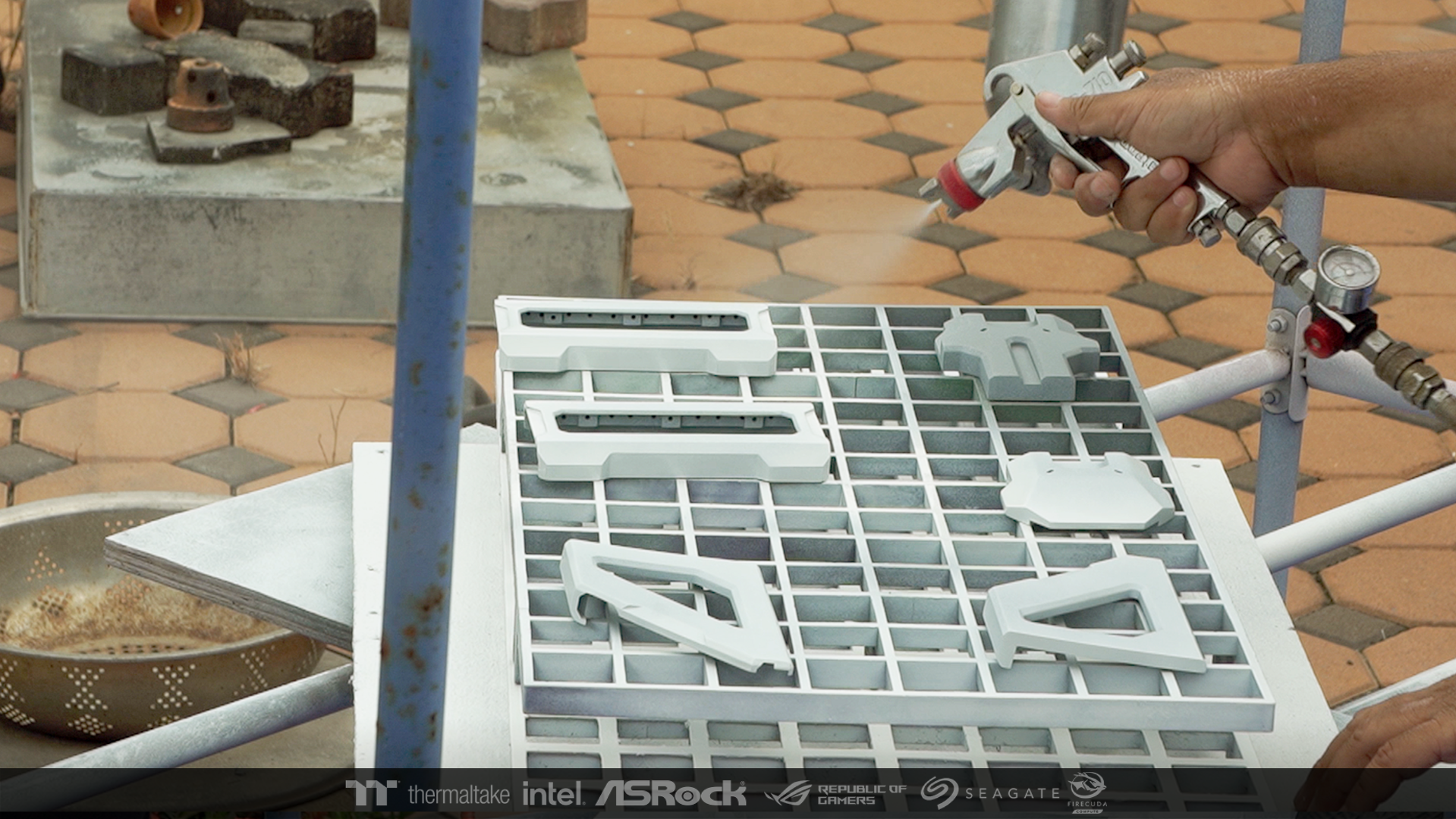
After the scrub is finished I took them and sprayed the primer. and sanded with fine sandpaper Now it's ready to spray the real paint.


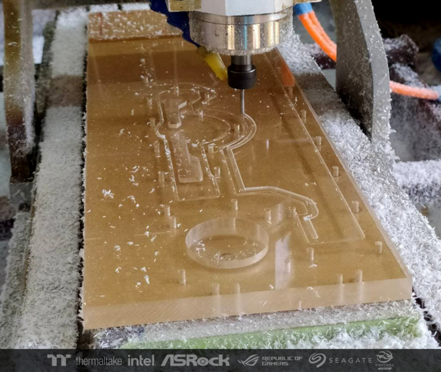
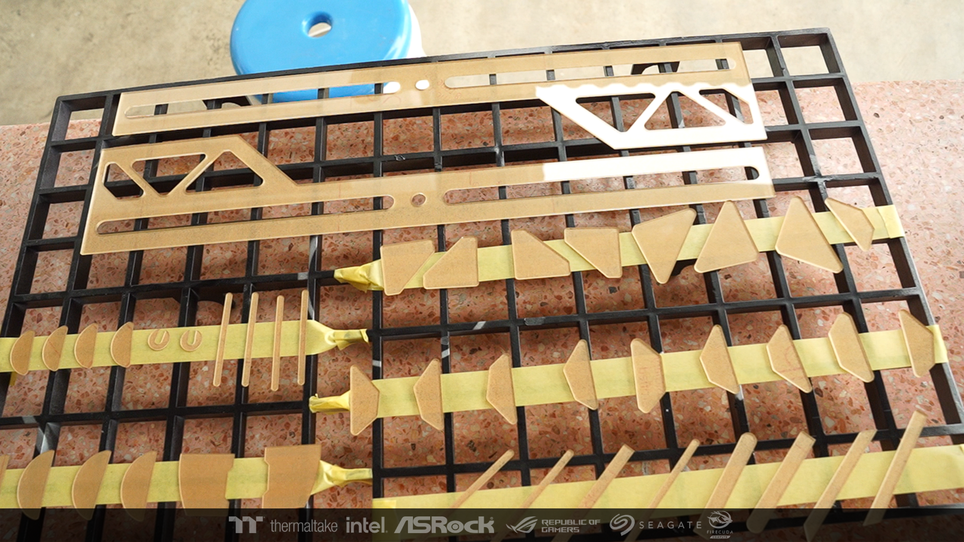
The acrylic patch is the same. Then cut it and bring it to prepare to spray the primer to paint together.

-
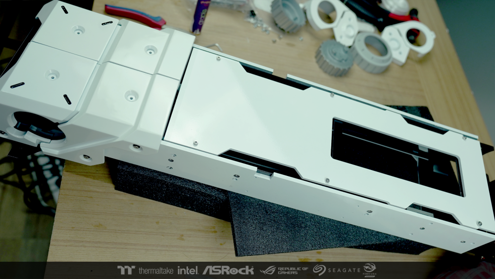
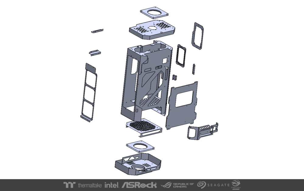
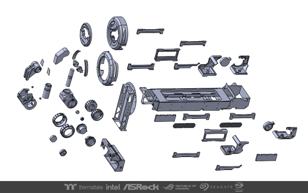
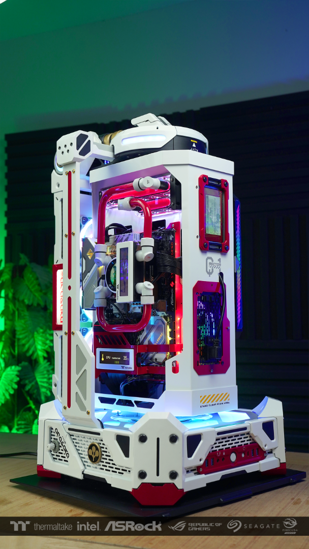
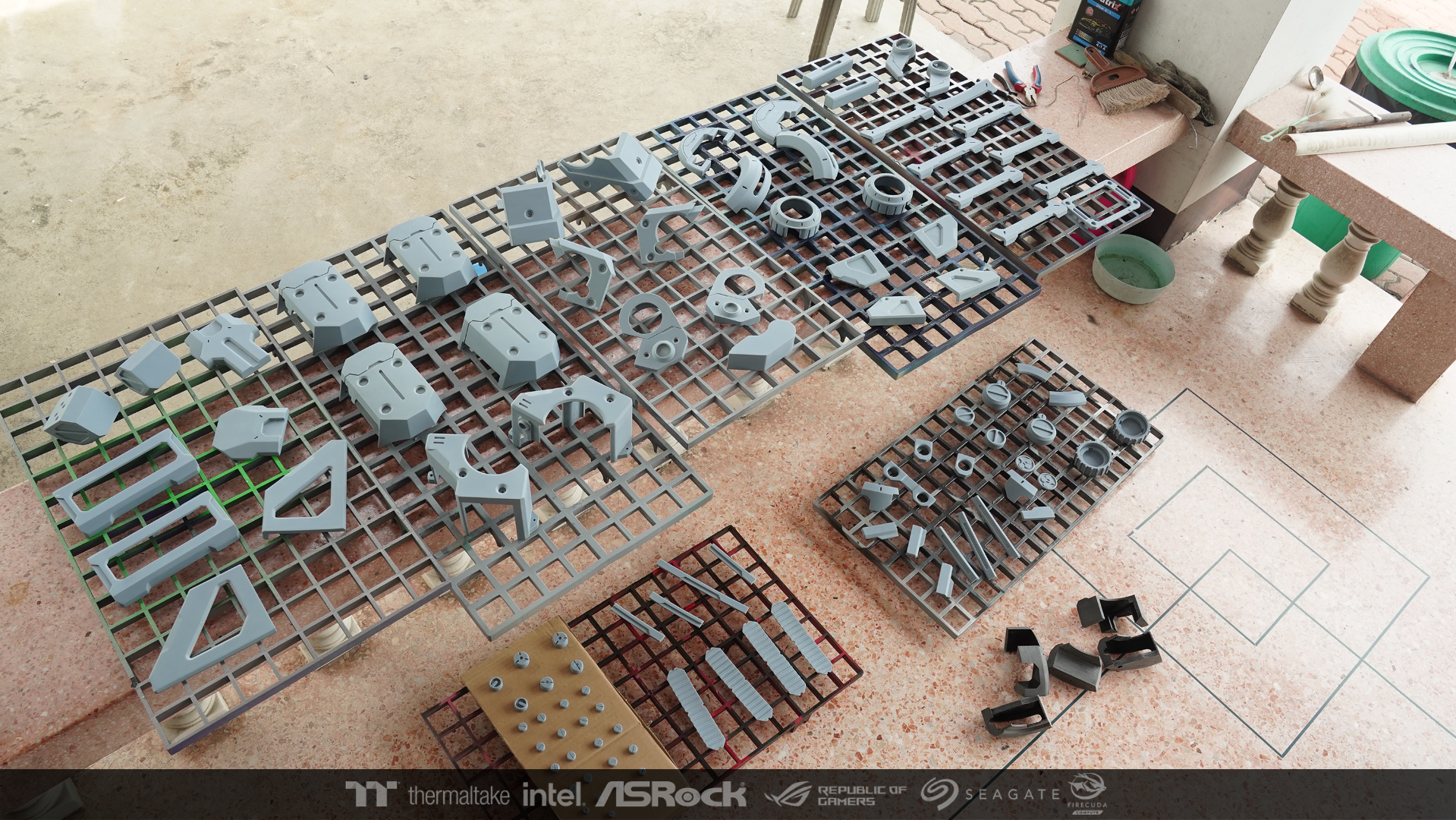
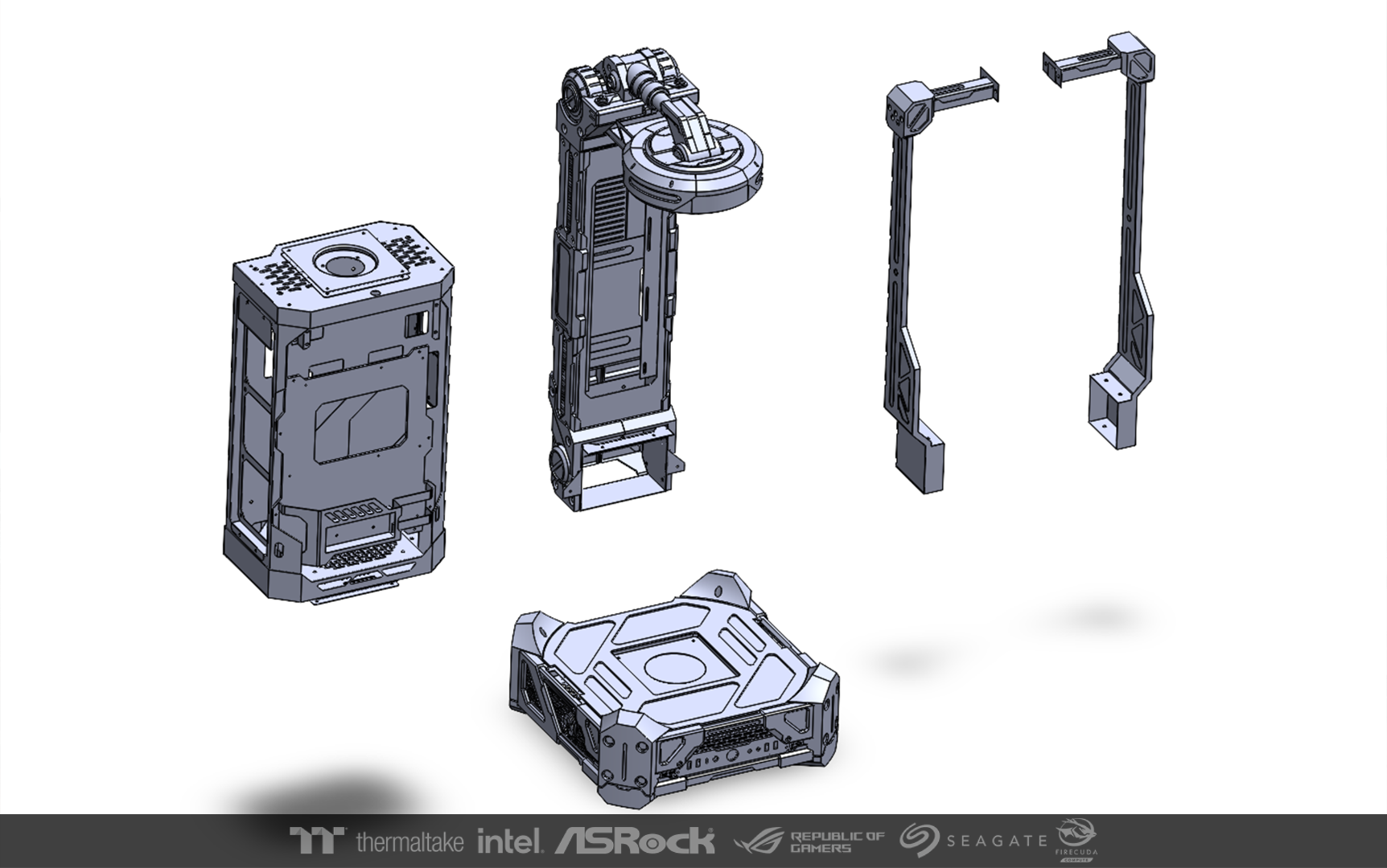
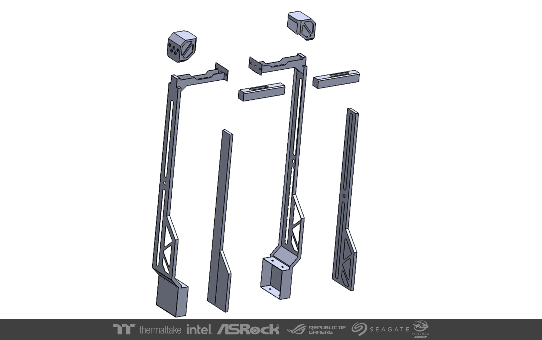
The next step is to create all the parts. The overview that I designed can be easily separated into 4 groups.
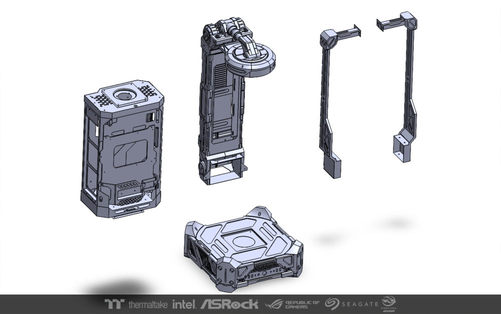
Each group has many different parts. The main components are steel sheet, 3dprint and acrylic. It took me about a month to design and write them up.
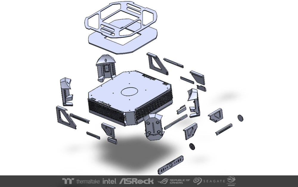
This part, I designed it as a light box to send the center stand out.

-
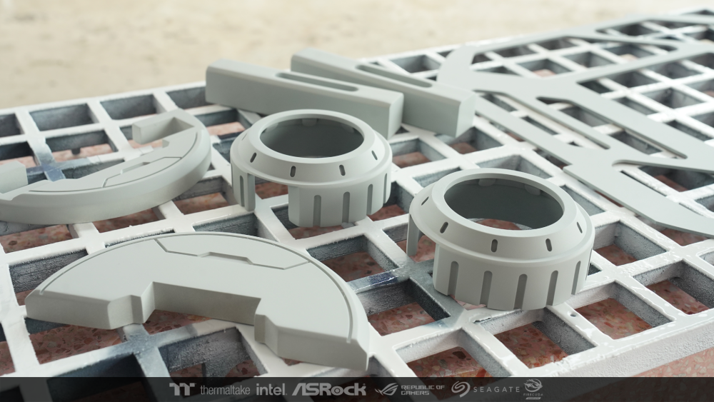
After test the balance. I'm polishing the putty until the surface is smooth. Then spray paint the primer to all structures and set aside.
-
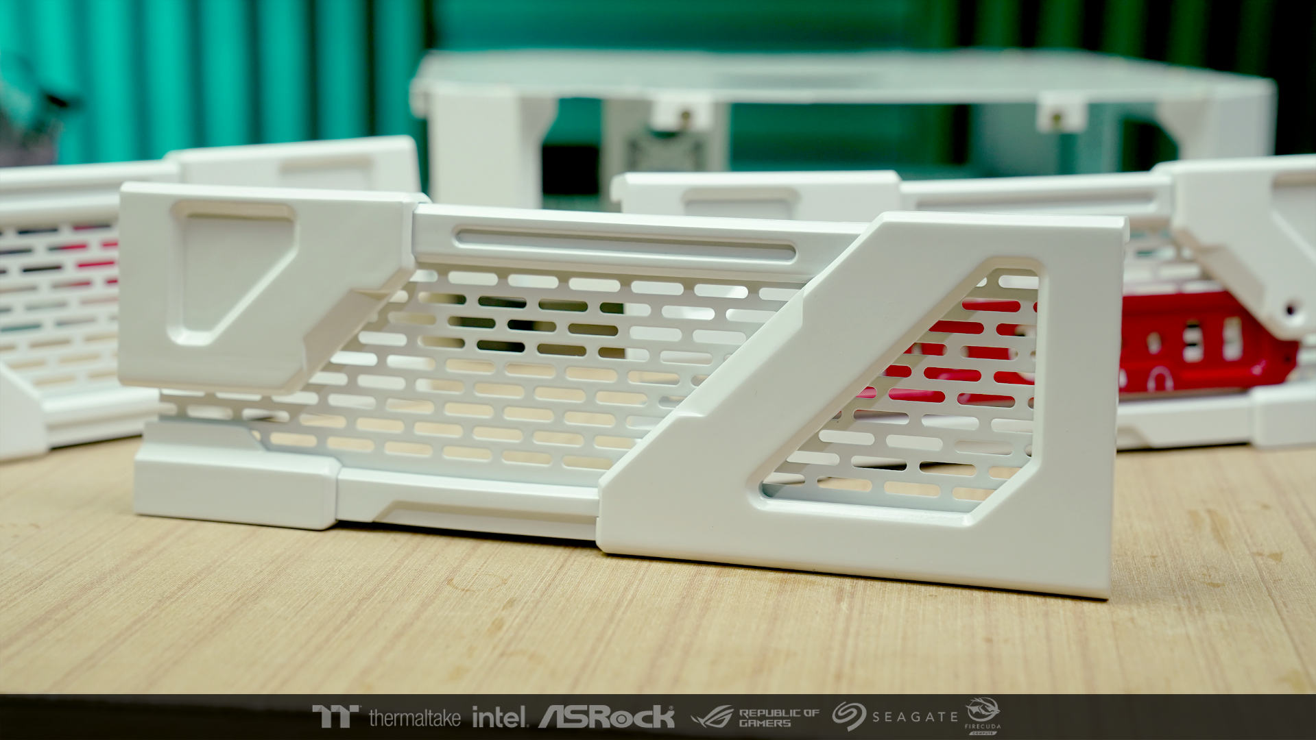
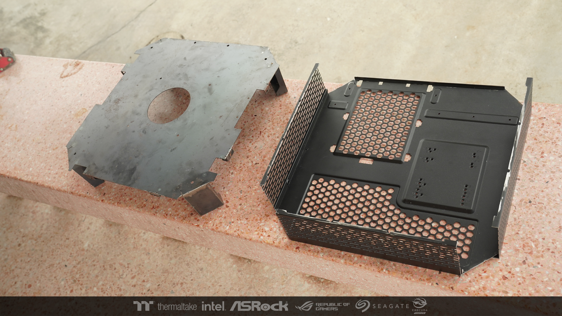
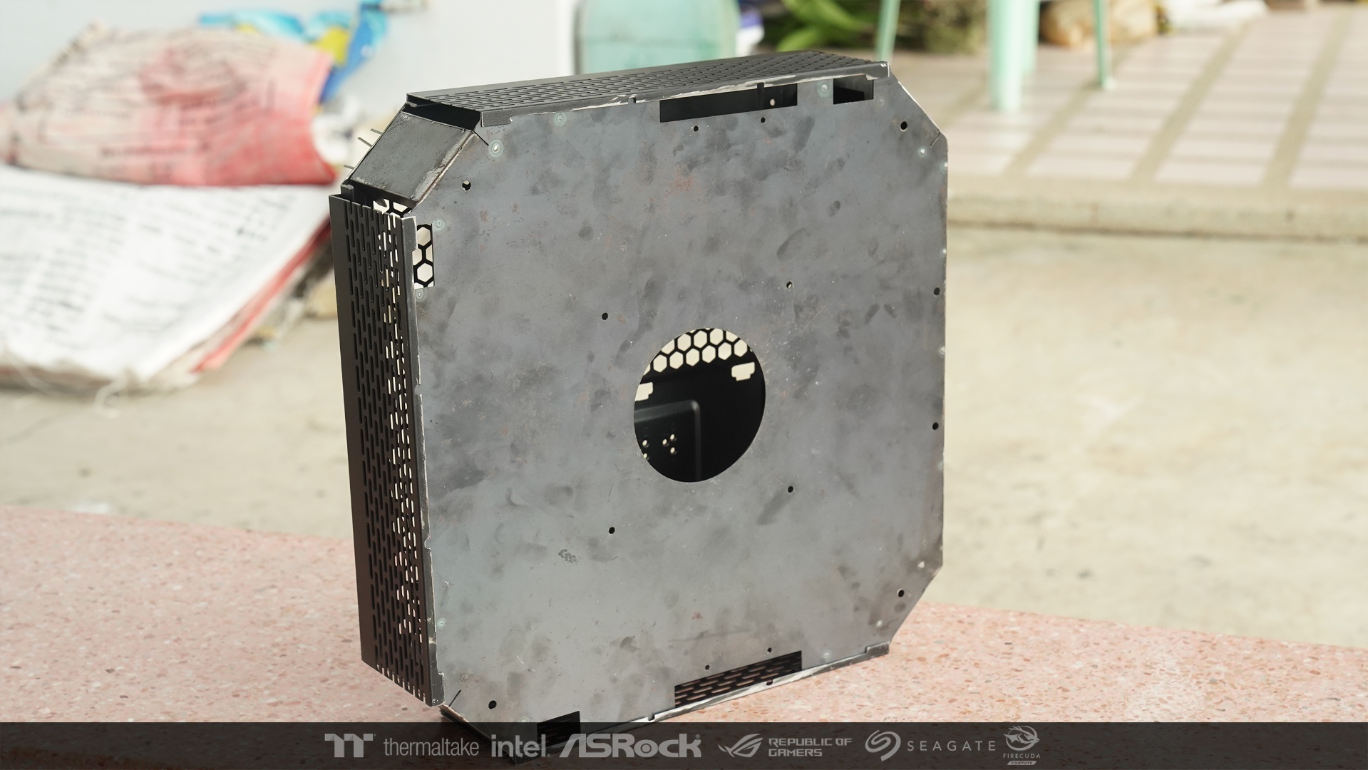
I took the part cut out and put it to test to check that the size, spacing and holes match the parts that I made new.

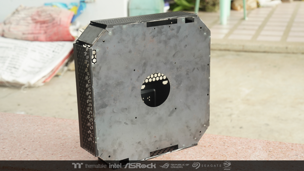
Because I cut off the 4 corners which are the load-bearing points and moved the point to the middle. So I must put the new part where the hardware is placed to check the balance of the new weight distribution. and test the operation of the bearings. Lucky !! It'a work fine. 😙


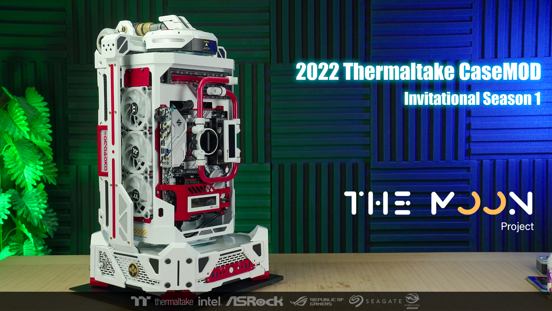


[Thailand] Krittanon Kidprasert
in 2023 Thermaltake NeonMaker Lighting Mix Invitational Season 1
Posted
The concept of this event is all from the anime. It's what I love.
I do this job with fun. And I hope you have fun together. 😁