-
Forum Statistics
93.2k
Total Topics114.3k
Total Posts -
Member Statistics
173,108
Total Members16,800
Most Online


Tech Geek
-
Posts
27 -
Joined
-
Last visited
-
Days Won
1
Content Type
Profiles
Forums
Downloads
Events
Gallery
Blogs
Everything posted by Tech Geek
-
I don't believe this to be a ThermalTake issue. The workaround seems to be isolating the controller from the ARGB out from the motherboard works, but it's something with ASUS software.
-
I had some weird software issues, but when I went into the Addressable Headers tab there were two headers showing and it was causing weird stuff. Most cases a reboot fixed it, but a couple times I just closed and re-opened Armory Crate (doing random or repeated things) and the second header disappeared. Most definitely there are still software issues, and there are bound to be more in the future. As for the hardware (controller) issue, it no longer causes the software to trip up and lock the Number or LEDs to 1 as there is no device driving the LEDs besides the motherboard. I'm sure this could have been resolved without the modification of the controller, but it appears that ASUS couldn't or more likely, had no real incentive to fix the problem with their software.
-
Mine is still working, but I'm showing an update in Crate. It must be recent because I was just in there yesterday or the day before and it wasn't showing any updates. It is showing one for the ASUS HAL Central and Aura Kit. So I'll probably hold off on updating those for now. Have you tried rebooting. I've had odd behavior that seemed to sort itself out after a reboot.
-
To be honest, I think it's ASUS software at fault and not TT's controller/case. The Number of LEDs shouldn't be locked out by whatever stops it. If it worked properly, you should be able to set that value and it just works. Whatever ASUS does during startup/powerup causes this value to lock at 1, and even though it will let you change it, it reverts to 1 after changing it. If the issue was between their case / motherboard / software, it would have been fixed already. Since the issue comes about when mixing a third party case, they can deny it's their issue and not invest any time and money resolving the issue.
-
I'm using Armory Crate, but I presume that Aura would work the same. I think Armory Crate is just a wrapper for multiple ASUS software, Aura being one of them. I also have played with Aura Creator to make some of my own affects. I'll be frank though, I've always found ASUS hardware to be excellent, their software on the otherhand is garbage. I wish someone would do a third party ARGB / RGB control software like Unwinder does for Afterburner / RTSS, or Speedfan / HWInfo / HWMonitor. I'm sure a third party could do it better. Make it hardware agnostic, like a drop down box for selecting the manufacturer (ASUS, GigaByte, ASRock, etc) or an autodetect sequence. I've even found in the past that ASUS software was causing random (and very infrequent) BSOD's that took running it down with Driver Verifier.
-
That's a lot of storage. Are you a photographer, content creator, or video editor? Do you find the vertically mounted GPU getting warmer? Looks pretty close to the acrylic side panel. I think I've corrected my negative air pressure in this case. It's probably closer to neutral now. I added a Corsair ML140 in the bottom of my case as intake. The issue was the three radiator fans venting out the panel side of the case was essentially venting all the air being brought in by the 2 X 200mm front fans. So if I hung toilet paper around any of the vent holes at the back of the case, it got pulled into them. The only place where the toilet paper was being pushed out was right where the rear 120mm fan is located. First I tried to set the pump / fans to a lower speed (the Fractal Celcius S36 has a fan hub that runs off one header on the motherboard with the pump) to see if I could get some airflow past the radiator, but it didn't help a whole lot. The addition of the Corsair fan seems to have balanced it. I could get it to go positive, but I would have to crank the Corsair fan up to where I could hear it (unacceptable). I guess another option would be to switch the radiator fans around to pull air in to the case, the grill there is screened. My preference has always been to have positive air pressure though all the research shows it really doesn't have much affect on the overall temps. Though I think specifically to my case, I wasn't getting any fresh air past the radiator, so while CPU temps were unaffected, around the motherboard and further back suffered.
-
Very nice. I see you went ASUS / TT. Mines a bit of everything. I've got an EVGA SuperNova 1000 G2, TT View 37 ARGB, ASUS Prime x570 Pro, AMD Ryzen 3700X, ASUS Strix RTX 2060 Super, 16GB G.Skill Trident Z RGB DDR4 3200, Samsung 970 EVO Plus 512GB, WD Blue 4TB HD, Fractal Design Celsius S36. I kept the GPU and PSU from my last build. I was torn on this build, I've always built Intel for myself, I've built AMD for my kids, but never for myself. I also wanted an ASUS Strix MB, but it was just too expensive for what I was going to use it for. Overall I'm happy with my system. I was glad to get this RGB thing working. If I could get my system to POST with the advertised speed of my RAM I'd be even happier, but I think it's more of an issue with the motherboard starting the DRAM Voltage at 1.2V. Of course ASUS support won't even discuss the issue if the RAM isn't on the QVL. So I'm running it at 2933 (even divider keeps everything at a 1:1:1) which isn't too much of a loss of performance.
-
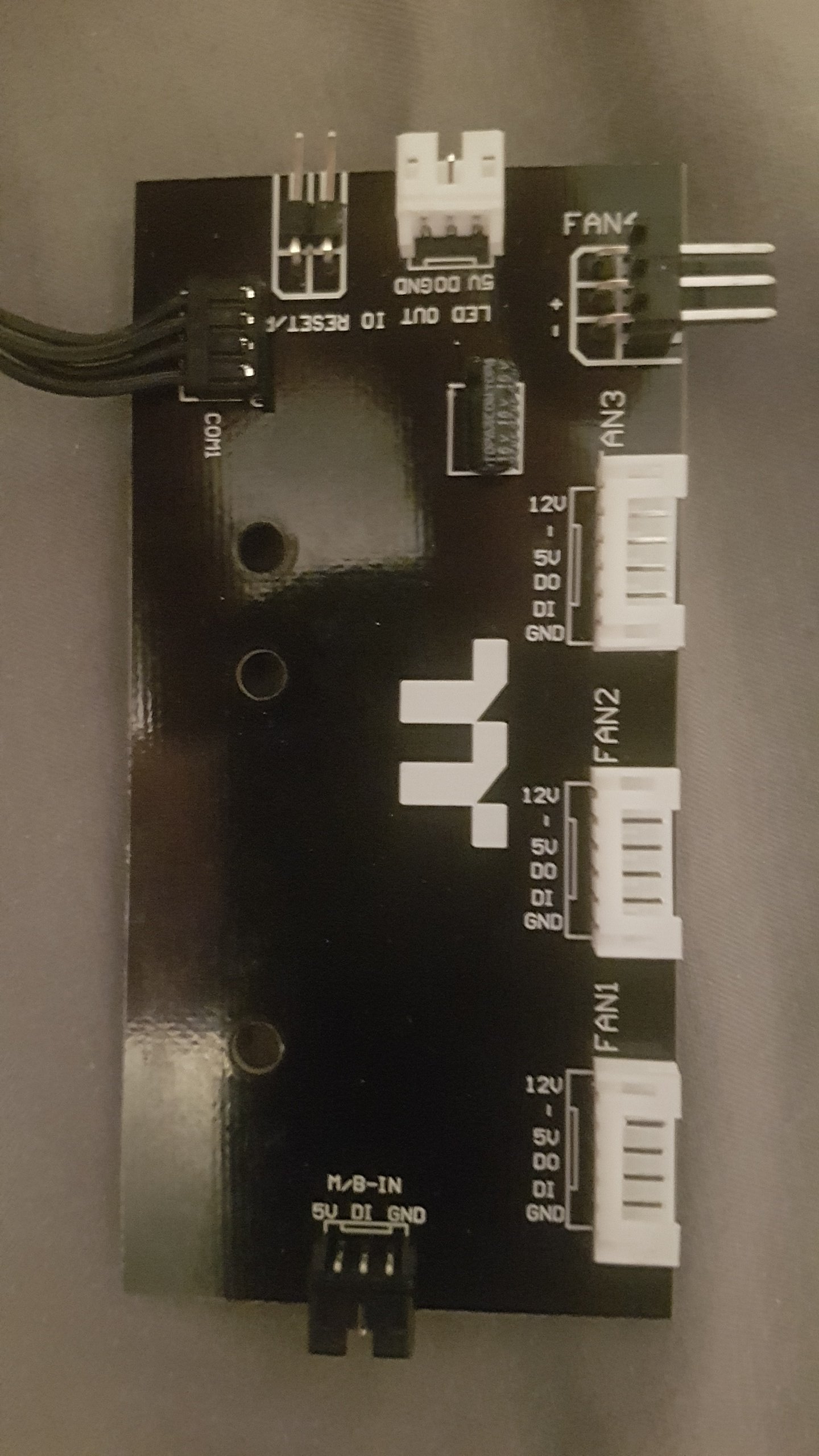
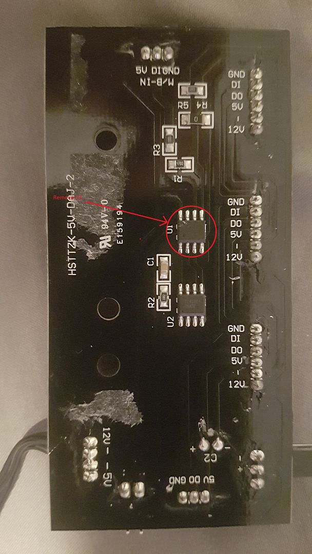
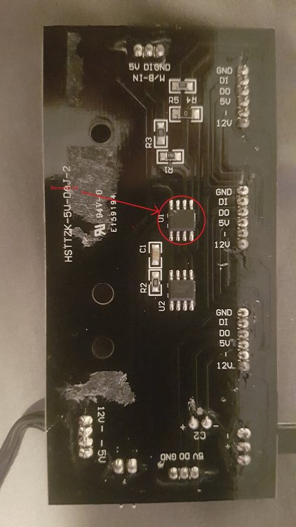
Ok, rather than remove the board from my system (which I really don't want to do), I've taken photos of the board TT sent me. It doesn't have U1 removed, but I've circled it for illustrative purposes. Hope this helps.

-
OK, I got tired of waiting on ASUS and them asking stupid questions rather than fixing their software. I have a relatively simple modification to the board that will get this working. After tracing out the circuit it's a simple matter of removing U1. Actually you could lift/cut the legs/pins 5 and 6, but removing it maybe easier. Once this is complete, the switch used to switch color/effect/mode no longer works, but I assume you don't want that functionality anyway. Actually you could repurpose this switch as a system reset switch. Just to be clear nothing else needs to be done. I've attached a picture of what the board looks like just so you can see nothing else needs to be done. No need to add wires, short anything, etc. The software will default to 120 LEDs, so if you don't want a gap in the effect (while it's talking to LEDs from 28 - 120) make sure to set that number to 27. Presumably if you have the right connector you could use the ARGB out connector (for the fourth fan) to run an ARGB strip. Of course you'd have to add those LEDs to the total.

-
I received an e-mail from ASUS support (generic), and they say they are working on it. I'm not holding my breath, but who knows. It's obviously an issue with their software, so it's their problem to work out. I'm willing to let them bang away at it.
-
Again as I stated awhile back, if load sensing were occurring, why does leaving the cable unplugged have any affect? The 5V line is presently open when connected the controller, which is essentially what you have when the cable is unplugged. So while I'll agree there must be something being done on the motherboard end to cause Armoury Crate to allow changes to be made to Number of LEDS field when the cable is unplugged, I still am not certain what is being done. Added my Police Cruiser effect I created in Aura Creator. videocompress-067-20200220_221607.mp4 20200220_221607.mp4
-
As to the above, the easiest place to put the resistor is push it in the back of the connector that plugs into the ARGB connector on the motherboard. You could slide the leads of the resistor down in alongside the sockets in the connector from the backside. CAVEAT: Any of this type of testing presents a risk as I and everyone else here have no intimate knowledge of the circuitry involved. I haven't done any reverse engineering of the motherboard, and I've only done very basic research on the controller (to ascertain that the 5V from the motherboard is connected to nothing on the controller) for my own interest. So if you use this information or my suggestions presented here, DO SO AT YOUR OWN RISK.
-
You actually have it backwards. If it's looking for a load (load sensing) on the 5V line, it will expect to see a low resistance. If it sees a high resistance or open then it would assume no load (0 or low number of LEDs). I did some inspection of the PCB and measuring. The 5V coming in from the ARGB connector doesn't go anywhere. The 5V out to the fan is being sourced from the SATA connector (verified with a multimeter). So if you want to use a resistor believing the motherboard is load sensing (which I'm not convinced is happening, but not certain), then you would want a resistor placed across the 5V (on the ARGB connector) to ground (any ground as they are all connected), not in series with the 5V line. This will place a load (presently it's open due to it not being used) on the 5V line coming from the motherboard. I would start with a higher resistance (1K) and drop it slowly until it reads something other than 1 in Number of LEDs. This is all with the presumption that there is load sensing going on here and Aura monitors it real time and not just at boot.
-
Well now that I sort of have everything Syncing so to speak, I've been playing with Aura Creator. Anyone else messing with this? I don't have any Aura compatible peripherals, but motherboard, RAM, case and graphics card are under Components. It seems that for now anyway, Creator treats ARGB as RGB meaning they don't make use of the addressable part. So for now all LEDs switch together. I have made a Police and Ambulance theme which was very easy. Essentially switching between red and blue (Police), red and white (Ambulance) in the shortest intervals available. Looks cool. I was hoping that I could do a 4 / 5 LED split on each fan and do the same, but for now the software doesn't seem to be that sophisticated.
-
I'm not sure if the motherboard or software is actually doing any auto-detection. I just found a tutorial from ASUS explaining the ARGB configuration and how to set it up this is the link: https://edgeup.asus.com/2019/how-to-get-the-most-out-of-your-rgb-leds-with-aura-sync/ Here is the excerpt from it that addresses how to set it up: Aura Sync treats our light strips’ addressable LEDs as one entity, for the most part. They’re all represented under the “Add Strip” label in the Aura UI. if you drill down in the software, however, you’ll find the headers identified individually. Each header supports up to 120 addressable diodes, and Aura needs to know how many LEDs are on each one to work properly. Configuring our build’s addressable strips in Aura Sync was as simple as navigating to the Addressable Headers section, punching the number of LEDs into the appropriate text box, and then clicking Save. It says nothing about it detecting it, it clearly says you have to tell it. So in our case why do we need to have the controller cable unplugged during boot for the software to allow us to adjust (and have it save) the Number of LEDs?
-
I've found that if I have MSI Afterburner launch with Windows it causes Armoury Crate to not detect my RTX 2060 Super. I don't know if this is maybe something to do with your losing sync with your graphics card. To fix this, I just stopped Afterburner from starting with Windows and then launch it after the Aura service starts. When I discussed this with the ASUS support person, he essentially said for the software to work I should only have Windows and Armoury Crate installed and nothing else. Might have been a language barrier, but I asked a second time if he was serious about nothing besides Windows and Armoury Crate installed (not just running) and he said "yes". Like anyone is going to build a $2500 CAD system for flashing a bunch of LEDs and nothing else. I already knew how to work around it at that point, I was just reporting it to him so he could pass it on to their engineers to look into. If it was some odd piece of software that no one else ran, I could see their reluctance in investing time into figuring it out, but millions of gamers use MSI Afterburner. As far as placing a switch inline with one or more of the wires, I'm still not sure how the motherboard / software detects the number of LEDs. It could be probing for addresses that respond if the data is bi-directional on the data line. Like "hey is there anyone one at 00, 01, 02, 03, 04,,,,78?" (78 being 120 in hex), but then that doesn't explain why when the cable is unplugged it defaults to 120. Same goes if it is detecting the current draw on the 5V line as having the connector unplugged would result in essentially 0mA of current. I'm sort of stymied as to why having the connector unplugged works at all. I guess you could try the ground line first as it should be the ground for the 5V and a signal reference for the data line, however it may get the ground via the SATA power connector. For me, I'm satisfied knowing how to work around it for the moment. I've reported the behavior to ASUS support so they can investigate it and I guess we'll see if they fix it. I don't shut my computer off or restart it very often.
-
Building on what you said here: 1. Once unplugged, the Number of LEDs defaults to 120. 2. After plugging it back in, as you said it works. 3. Changing the number in the Number of LEDs field now responds. ie: if you enter 9, only the LEDs on Fan 1 (all 9) illuminate, enter 18 and two of the fans work, enter 27 all fans work. So this seems to be a combination of a detection issue and potential an issue with the software not letting you override the value in Number of LEDs. Seems like this is fixable as it's very obviously a software issue. P.S. Very good find by the way. I'll forward this information to ASUS as I have a ticket open for this.
-
So I received the new controller board and the same issue remains. Only a few of the LEDs on the rear fan illuminate. I didn't received the ASUS MB to controller cable like I was told, but I'm certain that isn't the issue anyway. Who knows, it might just be the software. Is there anyone here that isn't complaining about an ASUS MB in combination with this configuration? I can't remember anyone saying they had a GigaByte or MSI MB with the same or similar issue. I do have an open ticket with ASUS which I will pursue further.
-
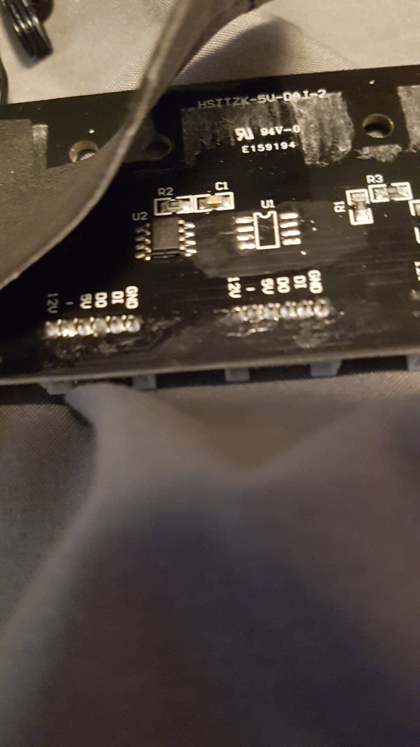
Many high speed serial buses are terminated at the end to eliminate signal reflection. They aren't connected directly to ground. Depending on speed and the impedance on the data line, you terminate the open (hanging) D(o) with resistor to ground. In our tools (at my former job) we had a serial bus known as the ITB (Inter Tool Bus) which we terminated with a resistor. I think it was 150 ohms if I remember correctly. Typically termination is needed when the transmission line is long, or when data speeds are very high. Edit: Looking at the back of the PCB hasn't helped much. The only thing I could make out is that it's got a 24C02 EEPROM (designation U2), but I can't make out any markings on U1 which I presume is a PIC or microcontroller of some type. I am less than impressed with the quality though. Looks like they didn't even try and remove the solder flux from around the fan connectors.
-
I can't be sure since I haven't gotten any specifics on serial transmit speeds or impedance on the data input, but if the serial data speed is high enough, it might be necessary to terminate the unterminated D(o) line to balance it. A lot of this is black box to the consumer. Takes a little bit of reverse engineering to see what is actually going on. I could give you a definitive answer if I had access to even a cheaper analog oscilloscope (even better with a digital storage scope) to see what the bit rate is on the data lines. Unfortunately I'm not working at a job that taps my skills right now and therefore have no access to the equipment I'd need.
-
Well apparently I'm getting a controller and cable. However I'm certain the cable isn't at fault as FAN1 seems to partially sync in Aura. When I say partially the LEDs that do light, and light with the correct color and effect. So that would indicate that its communicating with the controller board. I would suspect that the when switched to motherboard control, the controller is just a pass though to the fans. I'm wondering if the motherboard is unable to determine the number of LEDs on the fans through the controller. Inhibiting the communication / detect to the fans so to speak.
-
I'm an electronics engineer, I wasn't aware that it was auto-sensing using any electrical property (such as resistance). I think the LEDs are addressed via serial communication of some type. The 120 value is the maximum Aura allows in that field. I think what occurs is an "address" is send down the data line with reference to ground followed by data which corresponds to color (3X8=24 bits R-G-B). That's just a guess without getting an oscilloscope on the data line to see what's going on though.
-
That is weird. If I'm looking at the right case you have 2 200mm ARGB fans. I think there are only 9 LEDs on the perimeter of these fans.
-
I received a response from ThermalTake support requesting that I put in a RMA request for the controller and the cable. GregAMD, did you just get a controller? Or did you get both the controller and the cable from ThermalTake support?
-
Same issue here, I've got a View 37 ARGB case and a ASUS Prime X570 Pro. Only the fan plugged into FAN1 partially lights. It syncs with Aura though, it's the right color and effect, but only about a 1/3rd of the LEDs illuminate. The fans work fine with the controller doing the work, just not when controlled via Aura. As to the person questioning the noise, actually 200mm fans have a very slow top end RPM and are virtually silent. I can't hear the rear fan either. I wouldn't say I've got the hearing of a baby, but I'm not deaf either. Sure it would be nice if there was a PWM or DC fan control header on the controller board, but it's not really necessary. Edit: I've also reached out to TT support a few times and haven't heard anything back. I contacted ASUS support and they answered with a request that I connect the fans ARGB cable directly to the motherboard. I attached a photo explaining that the fans had a single connector for powering the fan and controlling the ARGB LEDs and explained that it couldn't be done. Well at least not without bastardizing the cable which would require finding a pinout. They said they'd look into it. Since this issue seems to be motherboard agnostic, the issue is probably ThermalTakes and not the motherboard makers hardware / software.