-
Forum Statistics
9.2k
Total Topics56.5k
Total Posts -
Member Statistics
137,722
Total Members16,800
Most Online
ThermalMike
-
Posts
1,020 -
Joined
-
Last visited
-
Days Won
46
Content Type
Profiles
Forums
Downloads
Events
Gallery
Blogs
Posts posted by ThermalMike
-
-
Arial,
Welcome to the Tt Community and thank you for your interest in our Core X9.
I have to say your timing is epic haha, as Thermaltake is just about to start (May 1st) our 2015 Thermaltake CaseMod Invitation where 7 modders are taking the challenge on the Core X9.
More Details: http://casemod2015.thermaltake.com
I wish you the best with your next build and we all cannot wait to see what these guys come up with!
- Arial_Moss and Tte Martin
-
 2
2
-
Give our support team a call and setup a case on it.
we can go into further detail on this and see if it needs replacement.
-
Hello,
Welcome to the Tt Community and thank you for posting up your concern.
Please let me know what email or how you contacted us with a link so we can check.
Are you using the AC Adapter that was included with the BlacX Duet?
Contact our USA Support for more information, the product may be defective. (See below)
Thermaltake USA Customer Service
Email: ttsupport@thermaltakeusa.com
Toll Free: 1-800-988-1088 M-F 9:00AM~5:30PM (P.S.T)
-
Hello,
Welcome to the Tt Community and thanks for posting!
They are different.
Check this review here on the SP-750M
http://www.techpowerup.com/reviews/Thermaltake/Smart_M_750W/
-
Hello,
Welcome to our Tt Community and thanks for posting up your concern.
Watching the video, did the grill get bent up where it is now hitting the fan?
This does not sound like bearings to me, it sounds like the fan blades are hitting the grill cover on the PSU or something is stuck in there.
Check that out and/or give our USA support a call, we do not give our customers a lower product, you will get the same product or something of equal or greater performance for replacement.
Here to help you if you need my support.
Thermaltake USA Customer Service
Email: ttsupport@thermaltakeusa.com
Toll Free: 1-800-988-1088 M-F 9:00AM~5:30PM (P.S.T)
-
Hello,
Give our USA support a call directly and we can look into this for you.
Thermaltake USA Customer Service
Email: ttsupport@thermaltakeusa.com
Toll Free: 1-800-988-1088 M-F 9:00AM~5:30PM (P.S.T)
-
BSSR,
Apologize the PSU you received seems to be DOA.
Thermaltake warranty only supports the original purchaser and any 2nd hand sales are not cover under warranty.
Suggest you contact the Ebay seller and request to return the product and purchase the product from an authorized reseller so you have warranty.
-
Thunder,
Did you find out what the cable is?
Also, check the manual or download it here, we have the pin-outs also detailed.
Let us know if you need anything else!
-
Thermaltake has a full line of power supplies to support your upgrade when you plan too!
http://www.thermaltakeusa.com/psu.aspx
 :)
:) -
####,
Great to hear!
Thank you for letting us know so we can properly assist you.
If you have any questions, feel free to msg me anytime!
-
####,
Thank you for the photos, I see you are in AU so I will forward this to our team there to help you with an RMA.
You do not have to leave the plug off for days, I just build the full kit in a Core V31, after basic purging and making sure all the air was out of the lines, I sealed it up.
Been going fine for weeks now, many things can happen, we can help with a proper replacement.
-
Hello,
Welcome to the Tt Community!
PSU will have different EPS connections, but are becoming more standard with the 4+4 type.
If you are getting the lights on the motherboard, you would need to turn on the system or jumper the PSU to "turn it on" before you get any voltage out of the connectors FYI...
The new PSU likely has a 4+4 connection, where it looks like a 8-pin, but it will split to (2) 4-pins.
Check and let us know the Part number of the PSU and we can review.
-
Great to hear!
Have a good weekend!
-
Hello,
The DPSApp software is compatible with the following Operating Systems:
Windows XP
Windows 7
Windows 8
Windows 8.1 -
Ost-Trieb,
If your motherboard has multiple USB headers, try the other USB header and see what results you get.
This could be a compatibility issue with the motherboard, since everything does work, but upon restart the connection is being reset.
Check bios and/or contact your motherboard manufacture to see if there is any option that will help.
Let us know what the model number is on the motherboard as well and we can look into it.
-
Hello,
Please send a message to our team through our Contact us and we can help to check.
http://my.thermaltake.com/ctGeneral.aspx
Please make sure to select the right region.
-
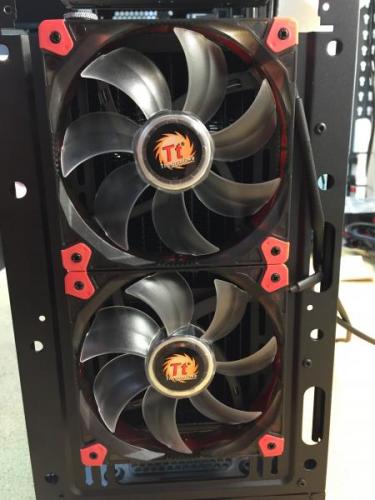
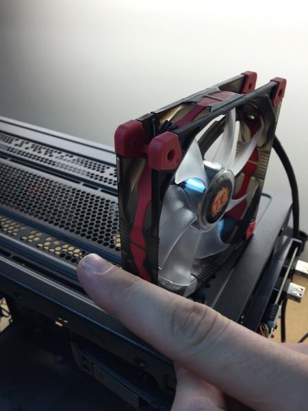
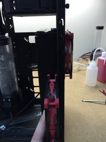
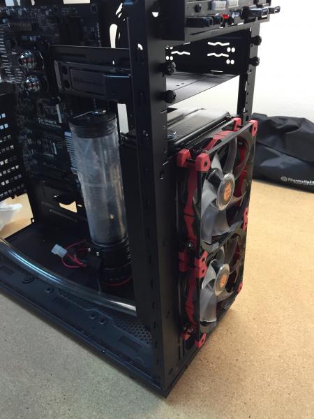
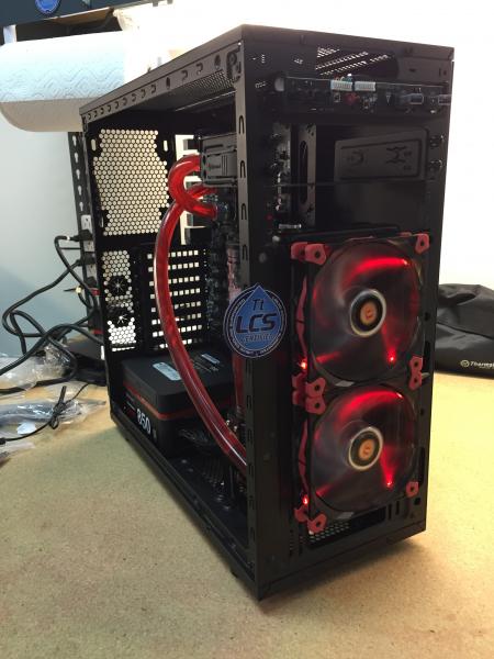
With our (PT40-D5)Pump/Reservoir, (W1)CPU block and (RL240)Radiator installed we can now install the fans for the radiator.
Make sure you first know the direction of the air flow on the fan

Now for this build, the fans normally install on the inside of the chassis, but since this is DIY..
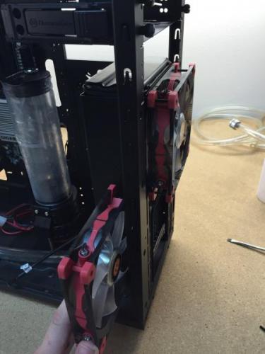

It is a tight fit and there was no issue with the front panel installed so I decided to mount on the outside giving me a little more room for the PT40-D5 to fit just right.
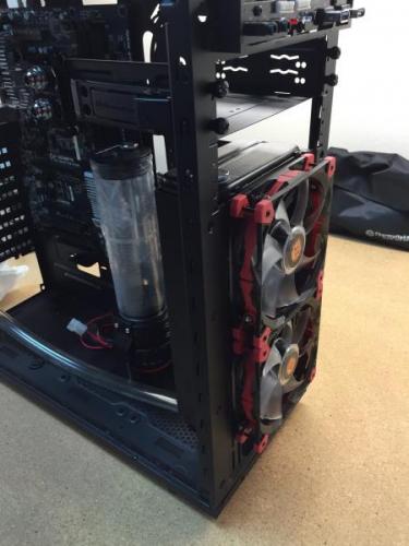
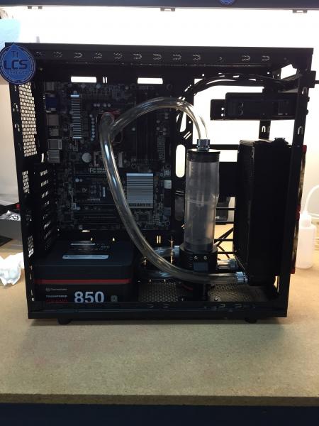
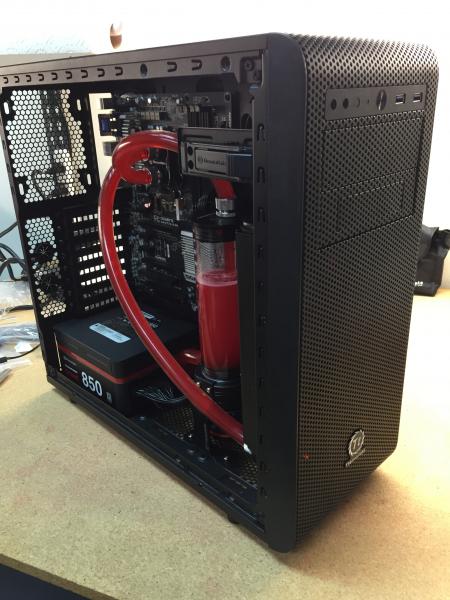
Moving back to the PT40-D5 will install the fittings and install into the chassis. (Make sure you have placement set where you want it first)


Here is the part where you come into the loop
 You will want to do a placement of all your components before you secure everything into place, some components you might have to remove and replace a few times until you get what you want. Take your time! You want to make sure you have everything installed to not only fit for your other components: PSU cables, VGA cards, HDD/SSD to avoid any issues AFTER you have everything cut and installed.
Take note on a couple important actions you need to do:
1. You have 6.5ft of tubing, don't waste making incorrect cuts or cutting too soon. Test and take your time.
2. Cut your tube as straight as you can to have the best seal possible.
3. Once you cut your tubing, use that piece for other routing to get a "Rough Idea"
4. When you have a tight spot (Like I did for the bottom port on the PT40) make sure you give enough room to avoid any pinch in the tube.
5. Secure the compression fittings with the tube pressed over the bard side as best as you can to assure a proper seal and avoid LEAKS.
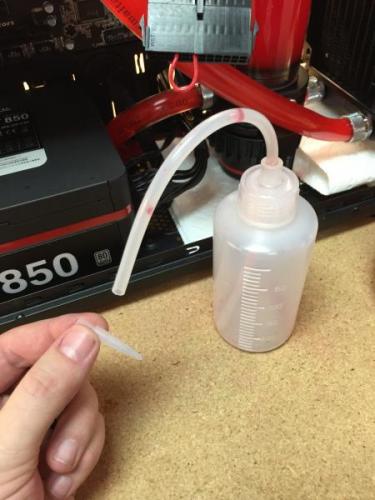
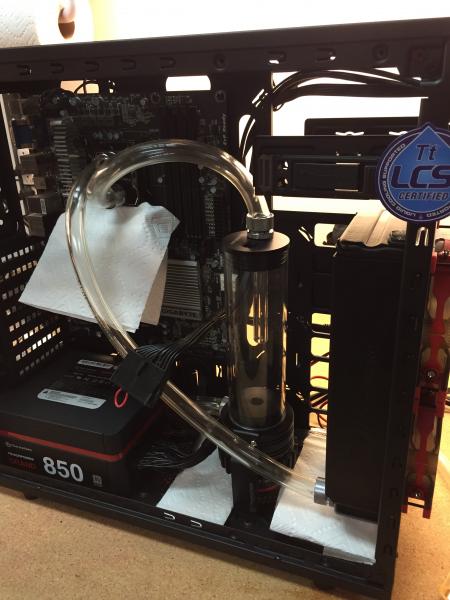
Before we start getting some coolant into our system, take some precaution to lay down on paper towels just in case we have any issue with leaks. Take the 24-pin jumper included to attached to your PSU as this will help with powering up the system without using the motherboard to turn the PSU on.

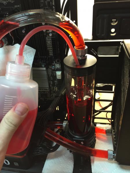
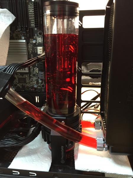
Take advantage of the filler bottle included with the coolant in the kit, you can remove the tip off the end for the bulk filling and then add the tip back on for more precision filling until you have the system purged and filled correctly.
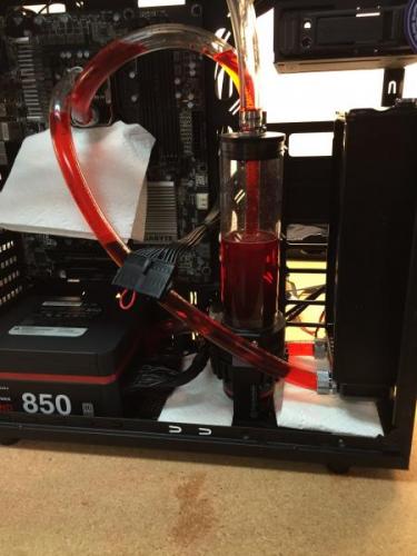
Start filling the PT40-D5 with the supplied coolant and you will see the reservoir start to fill and some of the tubing that is lower including the radiator.With the other top port removed on the top of the PT40-D5 I added coolant slowly.
Once you get the coolant filled above the inner tube in the PT40-D5 (Fill it above the inner tube about half way) you can now switch the PSU on and let the pump start to circulate the coolant throughout the loop.
**You will likely have to switch the PSU on/off a couple times making sure to turn it off once the coolant level gets below the inner tube length**


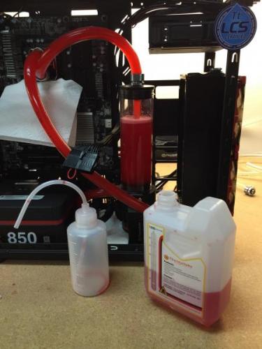
Here is what I had left after filling the system to the appropriate levels. You may have to add more later, let the system run and continue to check for any leaks.
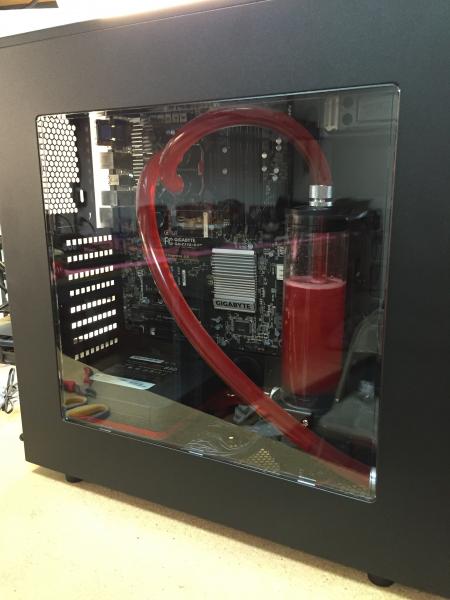
Once you have the system running for a while and confirm no leaks are present, shut off the system and reconnect the 24-pin to the motherboard and finish installing the rest of your components. Make sure all your cables are routed correctly when installing other components be careful to not put any pressure on your tubing or other component that could cause any issue with the seal of the coolant in the system.
This build was made using only the parts provided in the liquid cooling kit, Thermaltake offers many other parts including several different fittings like 45's and 90's to help with a even better fit. Plan out what you want to do, make sure you have everything you need and if you want to try DIY Cooling, think Thermaltake and let anyone here know if you have any questions.


- Tt Andy and Tte Martin
-
2
-
Hi everyone,
With the release of our Pacific DIY components and Kits, I wanted to provide a guide focused on the RL240 kit and take you through the installation process to give users an idea of what you will get:
RL240 Kit:
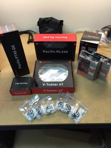
What you get:
- (1) RL240 Radiator 240x120x64mm
- (1) PT40-D5 Reservoir + Pump Combo (Includes Hardware)
- (1) W1 CPU Water block (Includes Hardware + Thermal Paste)
- (1) 4T 1/2" Tubing (6.5ft)
- (1) Coolant 1000ml (Red) + Filler Bottle
- (6) 1/2" ID 3/4" OD Compression Fittings
- (2) Luna 12 Red LED Fans
- (1) 24-pin PSU Jumper
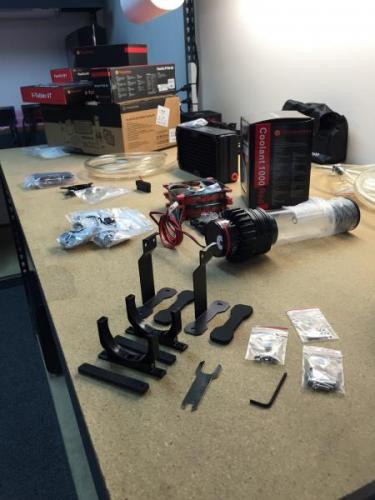
Here is everything out of the box:
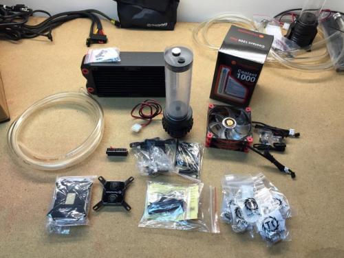
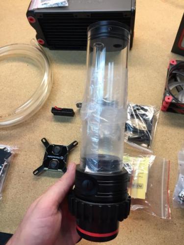
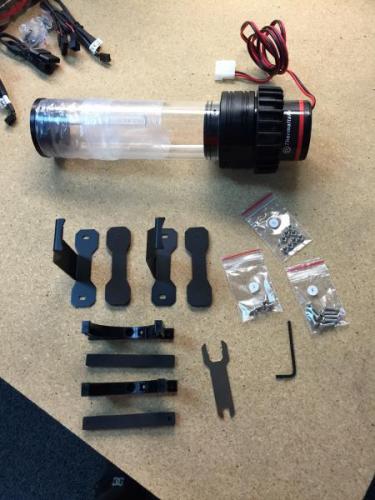
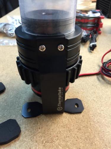
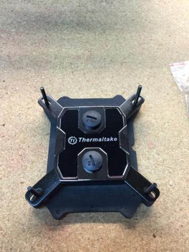
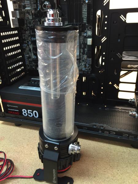
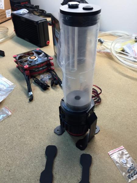
Here is the PT40-D5 Reservoir + Pump:
When you open the PT40-D5 packaging you will have all the accessories in bags including the mounting hardware. The brackets included allow you to mount the PT40 vertically or horizontally depending on the configuration you want to do.
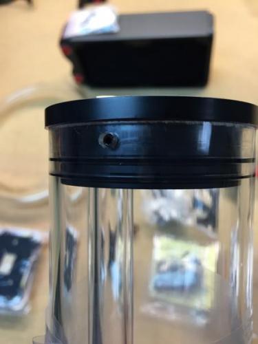
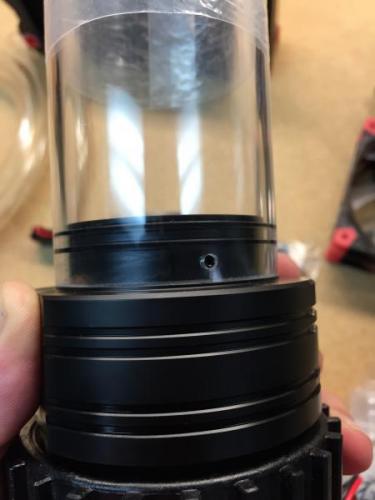
**VERY IMPORTANT**
There are set screws on both ends of the reservoir that are to secure the Tube to both ends, these screw do not need to be tightened. Also take note, if you plan to clean your reservoir later, make sure to remove the set screws (Both sides Top/Bottom) prior to removing to avoid causing any stress to the tube when separating. Also take care of the O-rings on both sides to make sure they are in the correct place when putting back together.
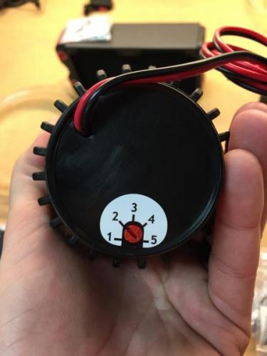
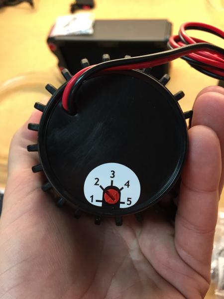
On the bottom you have the pump speed adjustment that should be set in the "2" position by default. I recommend leaving the speed adjustment alone until you have the system up and running to make any adjustments later. Turing the speed up is only needed when necessary, with the setting of "2" should be enough to support the default kit configuration.
Here is all the included brackets and hardware for the PT40-D5
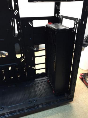
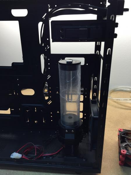
Since I am installing this in our Core V31, I plan to mount this vertically so I have installed the mounting brackets to the pump housing to secure into the chassis floor.

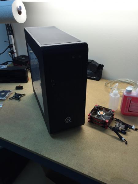
Here is a quick look at the Core V31 that we will be installing the RL240 kit

Getting ideas on how to place the PT40-D5. (Removed the HDD trays and the bottom ODD for clearance)

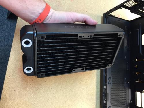
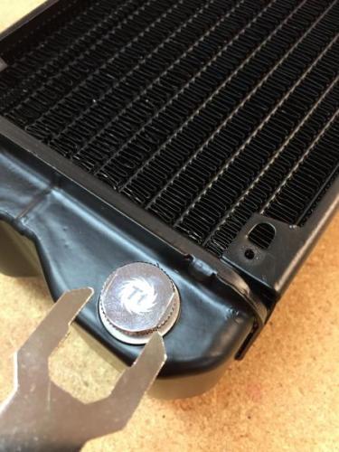
Now for the (240mm) radiator placement and overview. First you need to remove the orange plastic plugs that came pre-installed. Give the radiator a quick look and make sure everything is ok.
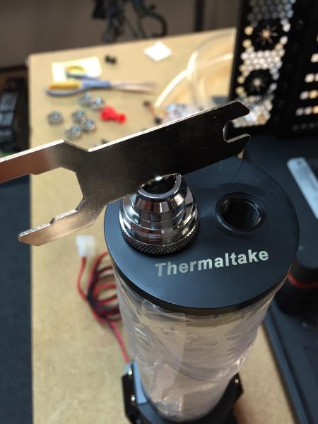
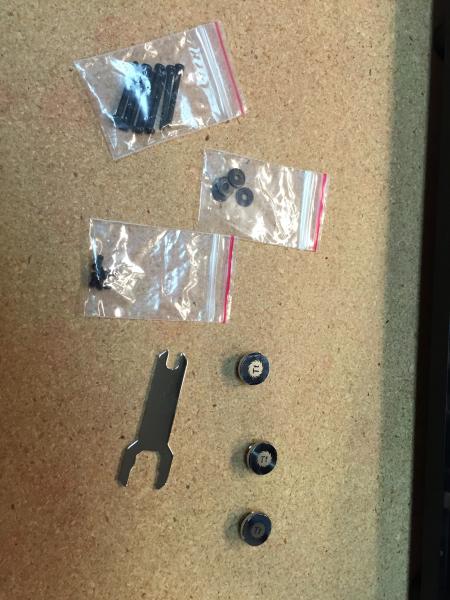
Here is the accessories that come included, you get mounting screws for the radiator and for the fans as well as (3) G1/4 port plugs and a wrench tool for easy installation.

Before you go through installing everything on the radiator, check the location where you plan to place it and make sure it will work out with the entire system including the water loop to make sure all your fittings and tubing will have proper clearance and your tubing will have proper flow to avoid the tube from pinching around a tight space. It is also a good idea before installation of your radiator to fill the radiator with distilled water and give it a good shake to remove anything left over from the manufacturing process. Fee free to repeat this step as many times as you want until you are satisfied.
You can setup the porting anyway you like, for this example I will use the (2) bottom ports on one side for my IN & Out and plug the other (2) bottom ports on the other side with the last plug for the top.
Note: Do not tighten the top plug port just yet, you may need to use it for a breather port when filling
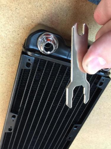
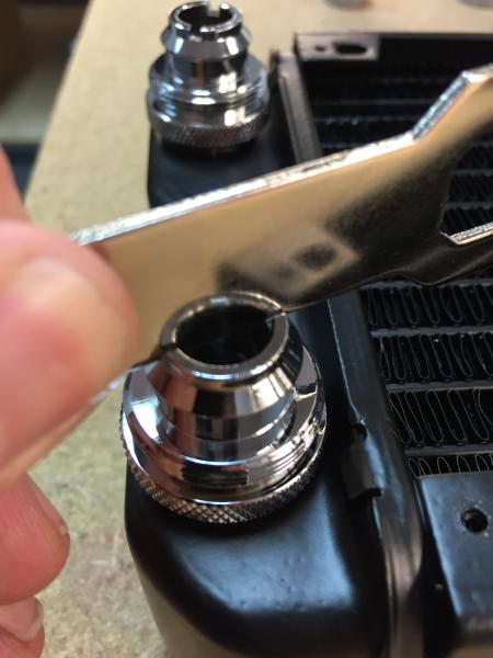
The wrench is a great tool to use for tightening the ports on your components as the fittings have "slots" on the top so you can use the wrench to tighten and avoid scratching the component or fitting using a standard pair of pliers.

The wrench also is designed to help secure the plug ports nicely. Remember, DO NOT over tighten, you will just damage the O-Rings if you gorilla grip the fittings into place. A snug fit is fine.
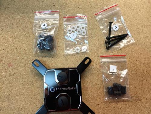
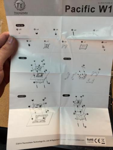
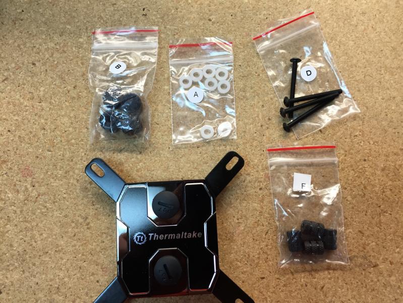
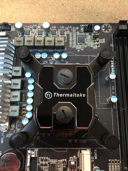
Now we take a look at the W1 CPU block to prepare it for installation to the motherboard. You will get a simple installation guide showing how to install for Intel or AMD type CPU's. Take note of the accessories labeled for each Intel/AMD.
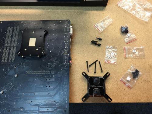
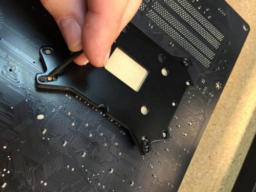
Now install the back plate to your motherboard and punch out the foam holes for your CPU Socket type to install the mounting screws to.
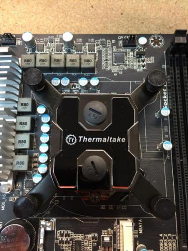
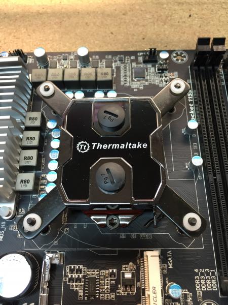
Once the back plate is installed and the mounting screws are through the motherboard, secure the CPU in place and apply thermal paste. Then seat the W1 CPU block onto your CPU first and make sure everything lines up correctly. When ready set the (4) plastic washers after placing the CPU block.

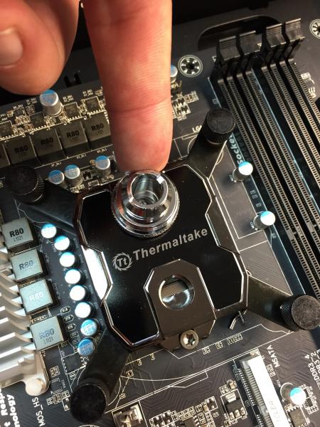
Then install the (4) screw caps and tighten them in the "X" pattern to apply appropriate pressure evenly as you secure the block. These only need to be hand tight and you should be able to tell when each one is secure very easily.
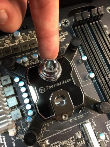
Now you can install the fittings on both ports, don't forget to use your wrench!
- EkbergDOF and Tte Martin
-
2
-
-
HammerU89,
I would send back the entire thing to replace, no idea what is effected Cord > Connection.
Don't guess on the issue and make sure you are safe always when something happens.
Up to you of course, our support is available if you need us.
-
HammerU89,
Looks like there is an issue with the cord based on what you say.
If it is having a loose connection like that I could see it also effecting the commands on the keyboard at the same time.
Please give our support a call today and we can setup an RMA for you to replace it.
We are open here in the USA for another 3.5 hrs.
Email: ttsupport@thermaltakeusa.com
Toll Free: 1-800-988-1088 M-F 9:00AM~5:30PM (P.S.T)
-
Totally understand, if I have any new information I will make sure to post it up.
Something to consider: (L x W x H)
Versa
H15 Dim: 15" x 7.8" x 16.2"
H25 Dim: 16.9" x 8.2" x 18.8"
Core Series
V31 Dim: 18.5" x 8.2" x 19.9"
In comparison with the H15, the V25 is not that much larger and same for the Core V31.
Plus you will have some extra room and more options for motherboard form factor if you plan to upgrade later.
I hope you find what you are looking for
We are always here to help if you have any questions.
-
Have you looked at the other Versa H series models?
H25:
http://www.thermaltakeusa.com/Chassis/Mid_Tower_/Versa/C_00002384/Versa_H25_Window/design.htm
I do not have an ETA on this product coming to the US.
We will continue to look into it, but there are no plans right now.
-
Mod Mod Mod!!!!!


Core X9 Mod/Builds
in Modding
Posted
I want to turn one into a fridge! haha