Leaderboard

Popular Content
Showing content with the highest reputation on 05/23/2020 in all areas
-

Project: I.S.A.C. by Andy Makin
ah_ah and one other reacted to Andrew Makin for a topic
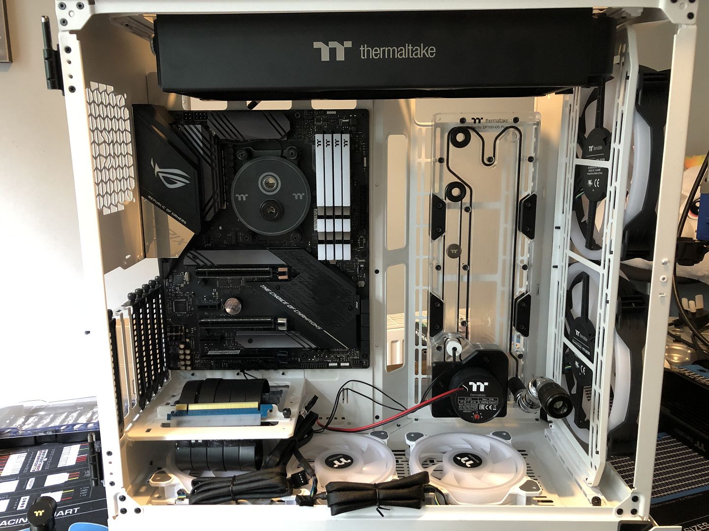
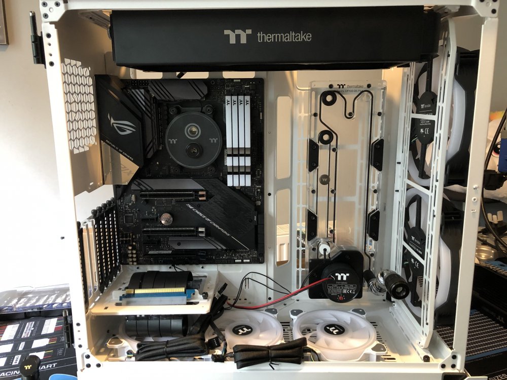
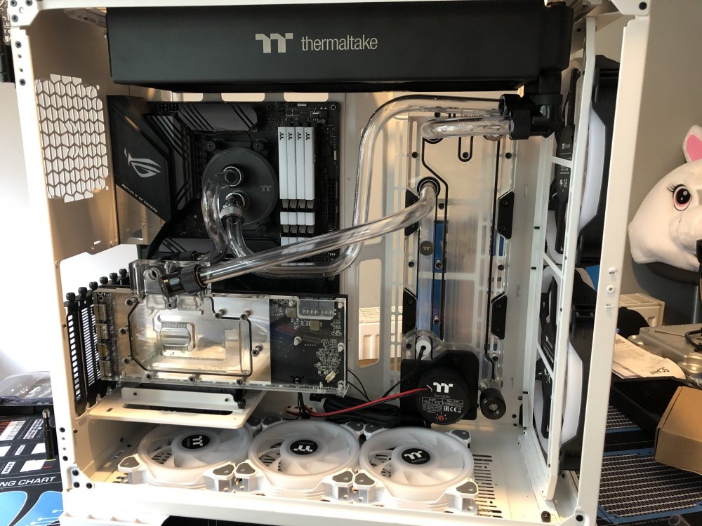
Gooood Moooorning Modding faaaaaaans! So with the motherboard heatsinks nicely brightened I couldn't just stick that black plastic shroud back over them. Luckily I have some 2mm aluminium laying about that I've had forever and this will make an ideal replacement. I started by tracing round the the original cover, but because it has mounting struts and other stuff underneath, this was better done turned upside down to get it flush(er) against the paper, which is why the drawing is backwards. Then I took measurements for the rest of the board so that I could expand it out a bit and cover up more of the motherboard. This is the area I want to cover, colour coding showing the original and then different additional bit that I might want to add. I did the drawing on card so that it would stay relatively flat once cut out and got it lined up with the mounting point and punched them through. Once on the board it didn't look right having a lot of square corners given the boards original angular designs, so I marked out bits I'd want tweaking with rough angles from the heatsinks. Back off the board I used the cover to get the proper angles and see about different levels of cropping. Couple of snips later and I think we have a winner! Now this was a fairly rough drawing so I then traced round this template in pencil and took to the drawing board to get all the lines true. Again I used the original to get the angled lines in, it was an awkward angle and I don't have anything like a sliding bevel. I could still find ones that were out like the one I circled in orange. With a couple of lines done this way I then turned the paper so the the angle was horizontal, checked them against each other to make sure they were correct and then filled in the rest. With the design completed I did a couple of photocopies and also scanned it for safe keeping. From right to left we have the original plan, the final design, the photocopy to be used as a template and the aluminium, with the original cover centre and glue to stick the template on. Only that's completely the wrong glue 😖 Looks more like spider spooge. 🤣 Still, it stuck that template down pretty good, if a little on the lumpy side. I also had to rub dirt around the edges where there was no paper to remove the tackiness of the glue and stop the jigsaw from sticking. That very morning I had been reading up on a cool little scratch build someone was doing as their first mod and advising themon how to cut outside the line and file in, so what do I do on the very first cut? Cut BANG ON the line 🤬🙄 It was the edge on the far right next to the SATA ports so wasn't a complete catastrophe, but was very careful and took my time with the rest and came out fine, although the small vertical edge under the angular protrusion top right was hard to get at. The Filing went ok, I'd bought a set of steel jaws for the workbench to clamp it in which helped keep it nice and steady. This tight angle was tough though as I didn't have a triangular file that matched or was under that radius. i had to edge in with the half round file, flipping it over every few strokes. A bit of folded sand paper helped get it a bit tighter, but it put up a good fight, Took a good lot of doing, had to go at it in a few goes to save me from injury. But was all this mess worth it? It fits! 🤘 There were a couple of areas that needed work that I highlighted in green, either to straighten them up, change the angle or stop it overhanging headers I'll need access to. Bang on. 👌 To get it to sit flush in the recesses of the M.2 heatsinks I needed to drill holes for the screws holding the heatsinks down. To mark where they were I put masking tape on the back, coloured the screw heads with whiteboard marker and pushed the piece onto them, being careful that it lined up with where it needed to sit. Seemed to work well. I used a punch to mark the centre and make sure the drill bit didn't wander. I thought the screw heads were 4mm so I drill a hole with a 4.2mm bit to give a little wiggle room, but I must have measure the wrong screws (the ones that will mount this to the motherboard i think) as they were a little too small. I needed 5.37mm holes minimum. My step bit had a 7/32" step which is 5.56mm and would do the job nicely. Unfortunately, due to either a wandering bit or inaccuracies in how I got the positioning the top hole was just out. 😞 To be honest I wasn't THAT upset. There were a few edges that were a bit naff and there were a couple of tweaks I wanted to make, so I widened those holes a fair bit so I could get it into place, check the fitment elsewhere and make sure the markings for the mounting holes were accurate, which they were. And just for fun I took off the paper and gave it a really quick and dirty "brushing" with a washing up scotch pad, but was mostly just from trying to get all that nasty glue off. Still looks pretty tasty 😍 It's a shame it's going to end up in the recycling, but for a first whack it's not gone too badly. I had prepared myself that it might take a couple of goes to get it right and with the design tweaks for Mk II already in my head, I wouldn't have been happy till I'd redone it anyway. So stay tuned crap fans! Plenty more of Makin's metal manipulation to come. Same Crap time, same Crap channel.2 points -

Chris Connor - Project SparklePony - #TTUK2020CaseModChallenge
ah_ah reacted to AcuteJungle66 for a topic
Thanks mate. After mulling it over though, I’m just not happy with it. It has become way too ‘busy’ due to that thick rad. I think I’m just going to bite the bullet and put it up top with the fans off-centre: For the components that are in there, a single 64mm radiator should be more than enough. So if I just go with the single: I’ll have much more ‘canvas’ and it should look a lot cleaner and less busy. At least that’s what I’m thinking; and my girls like it better this way, so I’ve got to listen to them! Whilst I did like the actual runs from the first iteration, this should work. Now we have a bit more space for whatever the #### we (I say we, my step-daughter is in charge of artwork) end up putting there.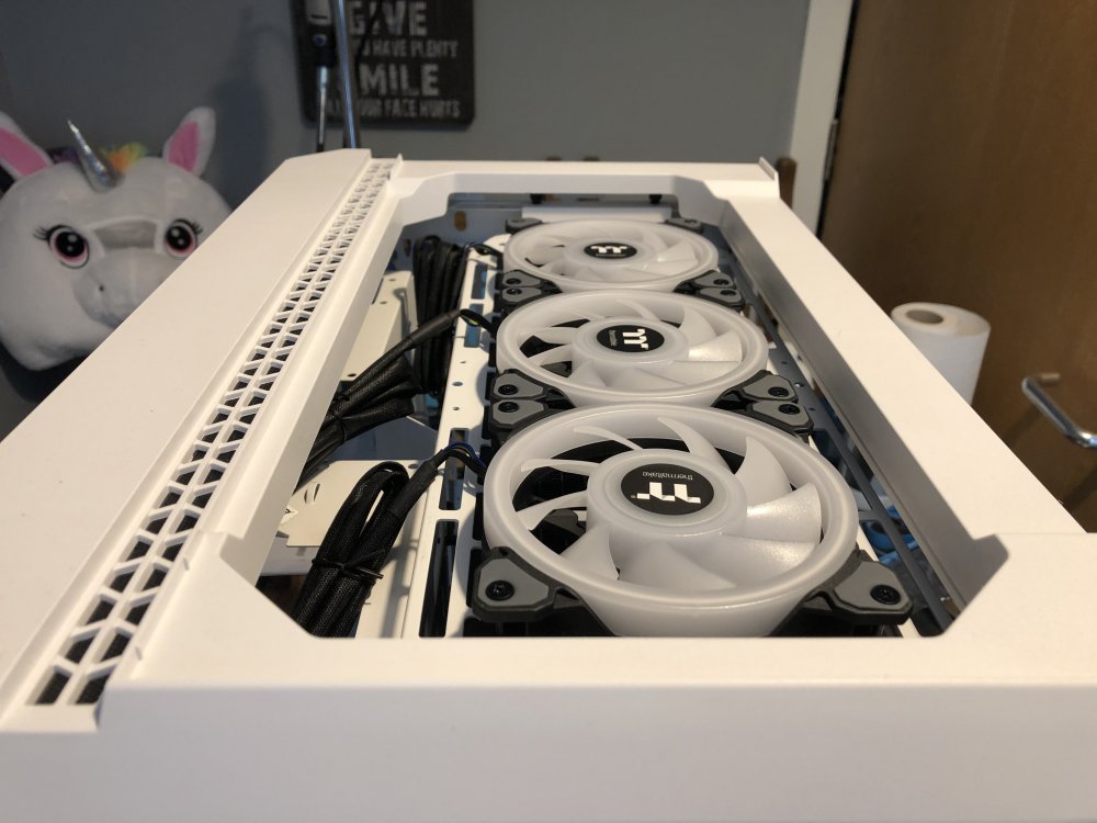
 1 point
 -

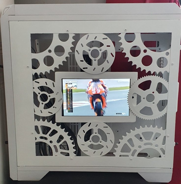
Colin McNally - project motogp
ah_ah reacted to Colin McNally for a topic
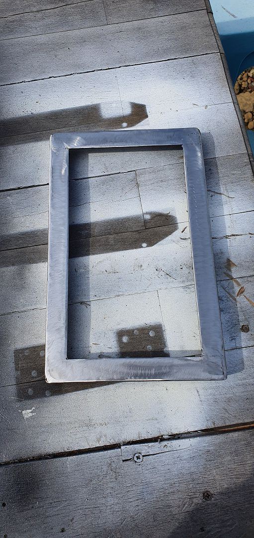
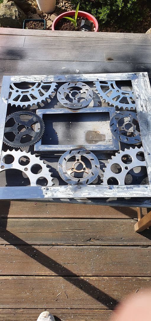
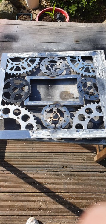
I cut the middle out of the back panel welded a frame then added some more sprockets and brake discs and painted it all white then added the screen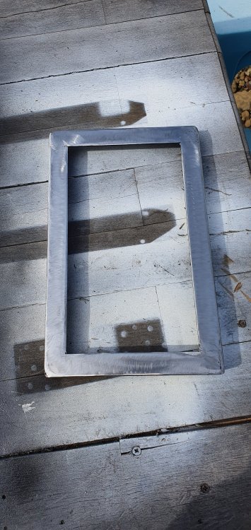
 1 point
 -
HSame issue, for about a month or two now, i saw it poped once but not for long then went off again trying to fix it now1 point
-
Also having the same problem. It's been like this for a couple months now at least and it really bugs me to see the rest of my lights looking so good and then the big dud right in the center ruining it all. Please fix this!1 point