-
Forum Statistics
94.3k
Total Topics115.9k
Total Posts -
Member Statistics
172,858
Total Members16,800
Most Online


jujunet
-
Posts
27 -
Joined
-
Last visited
-
Days Won
1
Content Type
Profiles
Forums
Downloads
Events
Gallery
Blogs
Everything posted by jujunet
-
Hi, Just to say I bought this item and, along with my homemade cable, I can now control fan speed : https://fr.aliexpress.com/item/4000037964860.html I also updated my MB to the latest bios, as suggested by Turritopsis, but I didn't tried to see if the issue is gone with my system. I prefer control my RGB fans directly by the motherboard with my cable, without the TT controller, and control fan speed with the 4 pots controller. I unmount the bracket, isolate the back of the card with electrical tape and placed the card just below the SSD place on the right side of the case, behind the MB (by moving a spacer).
-
No answer yet. I made a warranty friendly cable, work like a charm. Take a look to my post here :
-
Hi Fusion_DE. I thought about that too. There is no tacho and PWM wire on these thermaltake fans. So unfortunately, we can't use DC control and PWM control directly. It may be possible to plug the fan connectors of my cable on a hub with manual regulation (rheostat for PC fan). Something like that : https://fr.aliexpress.com/item/4000037964860.html Theses items modify the feed voltage of the fan using a variable resistor. there is also some regulators with temperature probe : https://fr.aliexpress.com/item/4000191008905.html But I don't know if it can work. I don't know how a PWM connector works. If the regulator need tacho information and PWM pin, that's bad. Ideally, we need something to decrease the voltage on pin 12V when idle, and inscrease when temperature in the case is increasing.
-
Hi, I posted a homemade cable diagram and tutorial to control RGB with the motherboards Asus X570. 15$ cost and save warranty. Jujunet
-
Hi, I posted a homemade cable diagram and tutorial to control RGB with the motherboards Asus X570. 15$ cost and save warranty. Jujunet
-
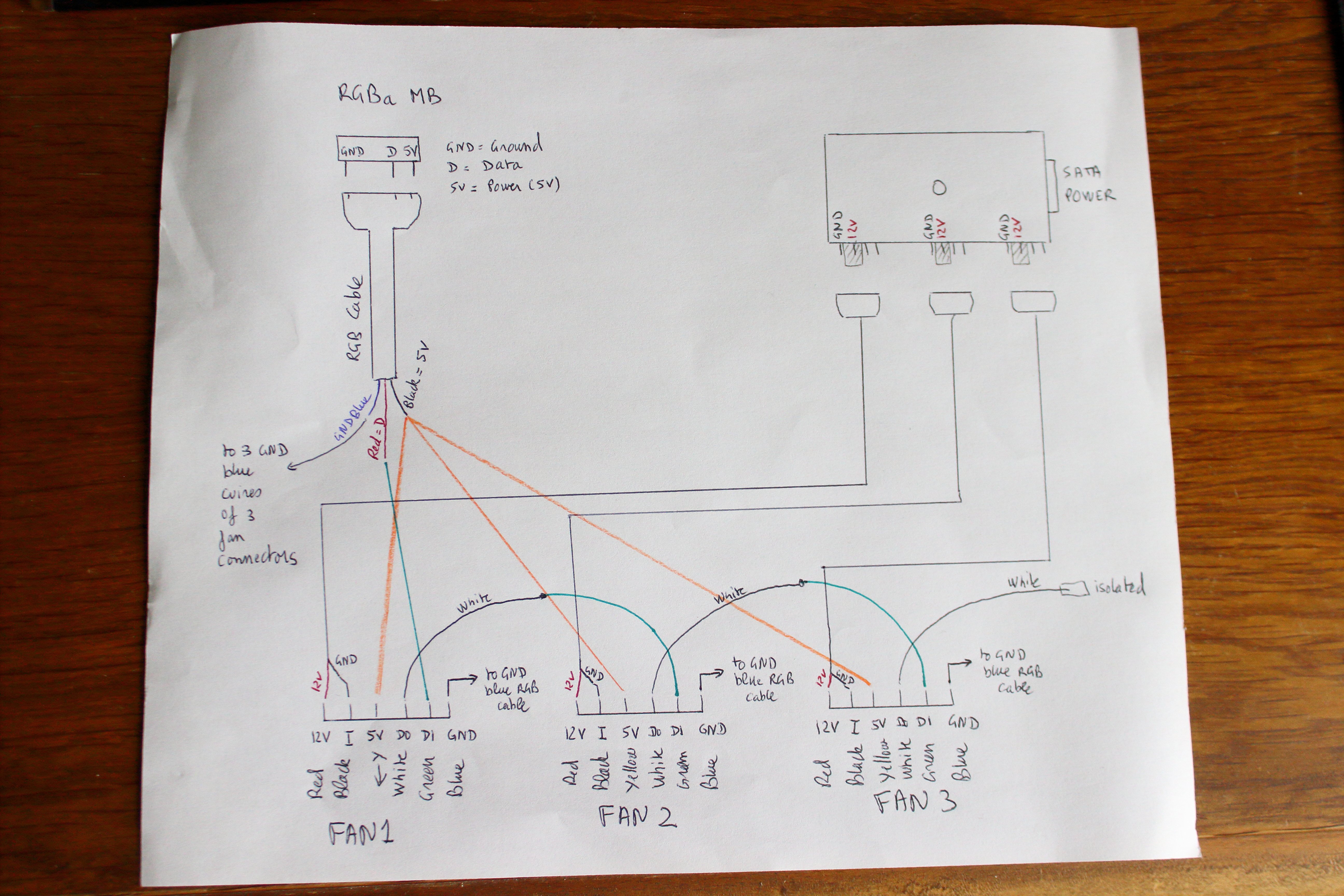
Hi, I have good news for those who want to create a cable and solve the RGB issue of TT Level 20 MT and other cases equipped with this controller card. I know TT still release new cases with this controller...🙄 Of course there is the PCB trick, but build a home made cable will keep the warranty of the case. There is also a possibility in the future that this issue will be resolved, if it's an software issue of Asus. In this case, you can roll back and reinstall the controller to have a full control with it and with the Aura software. I took a long time, because the shipment of equipment was very, very... long because of the coronavirus disease... Problem at shippment in China, and when the parcel of the last item was going in Europe. The french post stopped to work every days.😷 But now I made this cable and I can share the final tested wiring diagram and a video tutorial. I split the 6 pin TT connector to RGB + Fan power supply. The RGB of the three fans are wired in series and connected to the motherboard using a classic 5V adressable aura connector. The 3 fans are powered by a hub which is taking place of the TT controller. The hub is SATA powered, like the TT controller, to be sure to have enough power to run all. I give you the item list you need for that : Thermal sheath : https://fr.aliexpress.com/item/32997036798.html Aura adressable RGB cable 5V 3 pins : https://www.aliexpress.com/item/32989740896.html x3 PWM cable : https://www.aliexpress.com/item/32957428861.html PWM Hub sata powered : https://www.aliexpress.com/item/4000463360337.html 3 JST PH2 Connectors (sold by 10 items) : https://www.aliexpress.com/item/4000071997398.html Cost : approx 15$ Jujunet 😉 Video_tutorial.mp4
-
Great news Bryan, I tried something but, no luck. I tried to take own of the lastprofile.xml file (Total Control), and modify the line : <addressable_strip_led_count key="1">1</addressable_strip_led_count> to <addressable_strip_led_count key="1">27</addressable_strip_led_count> It seems that armoury crate modify this line when you enter manually the led number. But when you look somewhere else in the software, and you return to the led number page, it goes back to 1 ! I tried to lock the file in read only, but the software continue to display 1 even when 27 is always in the file... Other thing : I started to try during an half hour and I notice that my RGB header was unplugged, I forgot to replug it last time I took a look inside my case. And I had one led illuminated on the first fan ! The issue is same whatever the RGB header is plugged or not ! But of course no sync when unplug. EDIT : It seems like the line isn't modified anymore now that the RGB header is plugged. 🙄
-
Hi cplpunishr, Did you figured out why it wouldn't work when you wired directly the RGB header to fan ? It seems that your mod is same thing with the jumpers. Other wirings from fan 1 to 2 and 3 are going through the pcb tracks. It may be similar to my cable plan. Bad news for tacho, I will cable directly with sata 12v.
-
Hi, I used to looking for some system file or reg key with the number led information. My idea were to load a modified file or key automatically with a .bat file at windows loading. But I found nothing about that, no .ini file or something else. Look to regedit and nothing found. I will go to my solder iron and build my cable and say goodbye to the TT controller. 😄 Switch on RGB cable is a good idea too, but very tedious, you have to manually change led number.
-
Hi Bryan. I was talking about the cplpunishr's problem. He wired directly a fan to a RGB header of the MB and same issue. I did the same with 1 and 2 fans and get it work. My Idea is maybe the software kept the 1 led information like it did when it was plugged on the controller card. With stock config : When you unplug the RGB header, aura software change number of leds and when you replug it works until you shut down the computer. At each restart the software may reset itself and detect the led number. It can do a bad detection of led number when MB see the fans through the controller. When I was directly connected it seems to work normally after booting the computer.
-
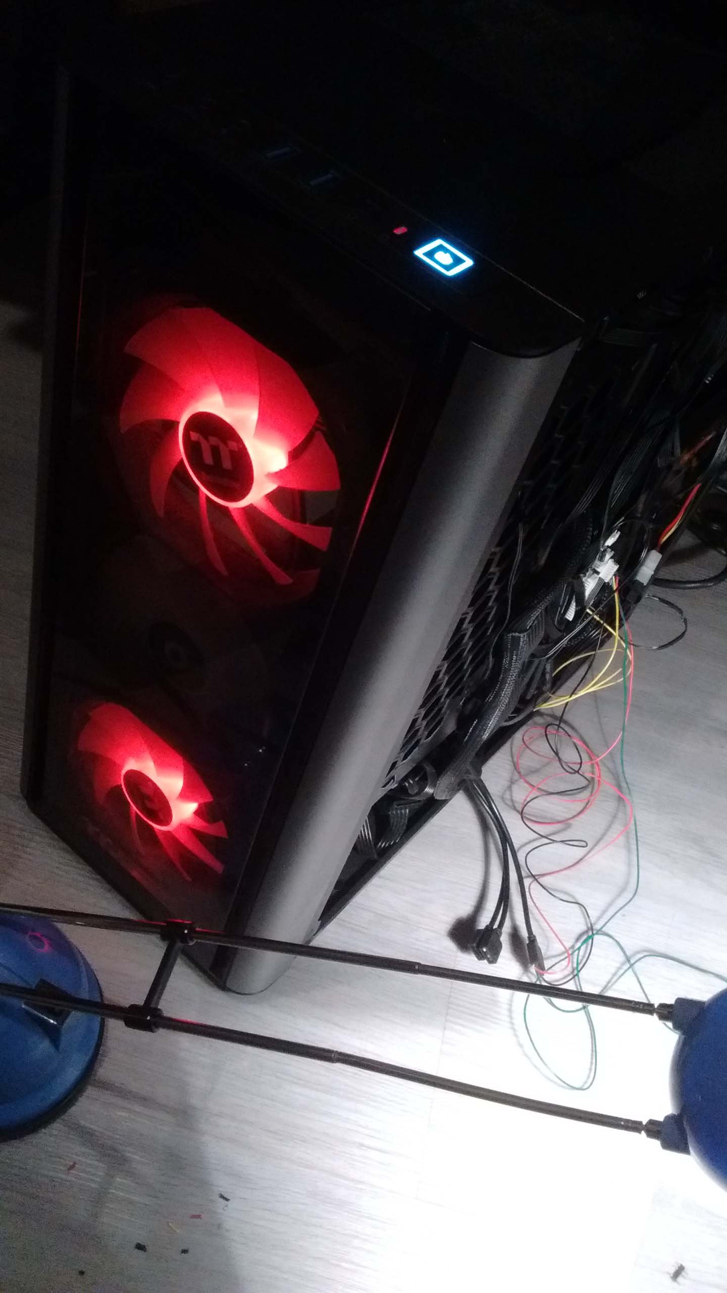
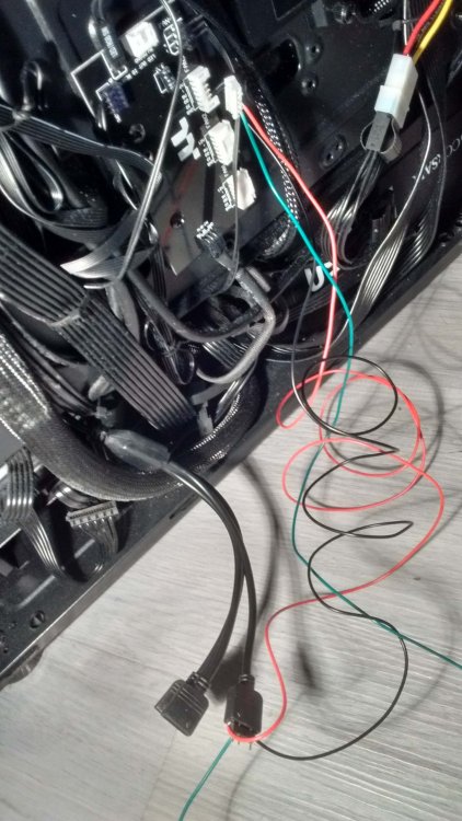
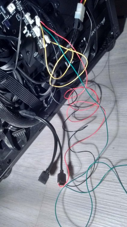
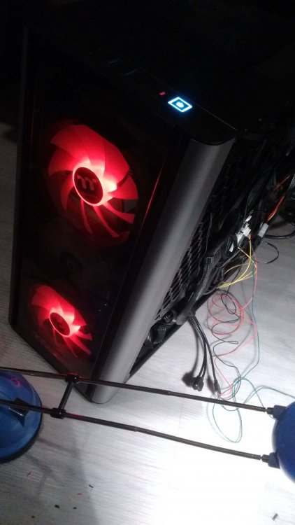
@CplPunishr: Hi, I'm very surprised, I just made some investigations and i did the same exact thing and that works very well : I powered off computer, switch off the PSU. Wired a 5V aRGB header to 5V of the third connector fan. Ground to Ground and Data to DI (first picture). The two other fans are still plugged in the TT controller card. -> I powered ON the computer and in armoury crate, I fixed the color in red to see well, and the first two fans were controlled by the controller card and the last with my MB. I powered off, switch off the PSU and keep the first wiring, i add : wiring the Data Out of the third fan to Data In of the first fan. Ground Fan3 to ground fan1 and 5V Fan3 to 5V Fan1. -> I powered ON the computer and the first and the third fans were now controlled by MB and the middle were off (normal, there is no Data in in Fan2 because fan1 is unplug) -> I changed in armoury crate fix red to rainbow, and, wwwwouuuaaaah, that works ! I'm pretty sure your Aura software had not reset correctly and kept the 1 led setting, or bad detection (loose connection ?). Did you used Aura or Armoury Crate ? Other thing : I plugged a 12V PSU to 12V pin and ground pin of fan, it spin. I had nothing on Data Out on the fans when I had one or two fans, and that works.

-
Thanks, great informations guys ! It seem that the three fans are really mounted in series for RGB data, and it confirms too that the chain terminate with the Led out connector ! The I pin has been plugged to ground because it's useless. Great luck that these fans are build like all RGB generic fans by same factories in China with other brands and all fans have same pins, then each choose DC+RGB, or proprietary connector. Tacho may be there, but not used ! My cable may work, if not, I will try a 150 ohm resistor between last DO and ground.
-
Hi Tech Geek it might be necessary to terminate the unterminated D(o) line to balance it It might not, why do you think about that : on the controller card, there is an unplug connector marked 5V, DO, GND. I have no cable that fit in this with my case, I found it strange since the start. It may be the output of the last fan on the chain, it may goes to an optional led strip or anything else ? We notice that it's the same format as the input connector MB/in, it may deliver the same signal like the input signal ? If it's true, the three fans may use directly RGB information from the motherboard, without alteration ? Closer look on card here : https://www.nikktech.com/main/articles/pc-hardware/pc-cases/9941-thermaltake-level-20-mt-argb-mid-tower-review?showall=1 If not, unterminated DO goes where ? To ground ?
-
Hi LCR_1992 Unfortunately, it seems that nobody who's own a TT case with this controller and a X570 Asus MB that works by default. I will keep you informed if I found a solution with my homemade cable. Delivery from China to France is pretty long, I think i will have all the stuff in 30-45 days. Another thing : I may not be a sofware bug of Aura or Amoury Crate, because the lighning should work even at boot. When we are under UEFI interface, that won't work ! It seems that bios isn't recognize all leds through the controller. Good idea to contact Asus : A simple bios update from asus may resolve the issue, because it works with X470 MB. Asus has probably changed something on Aura on X570 MB Unplug a fan won't work because on 2 fans cases with this controller, there is a jumper between DI and DO on the first connector. But then, the issue is carry forward on the second fan.
-
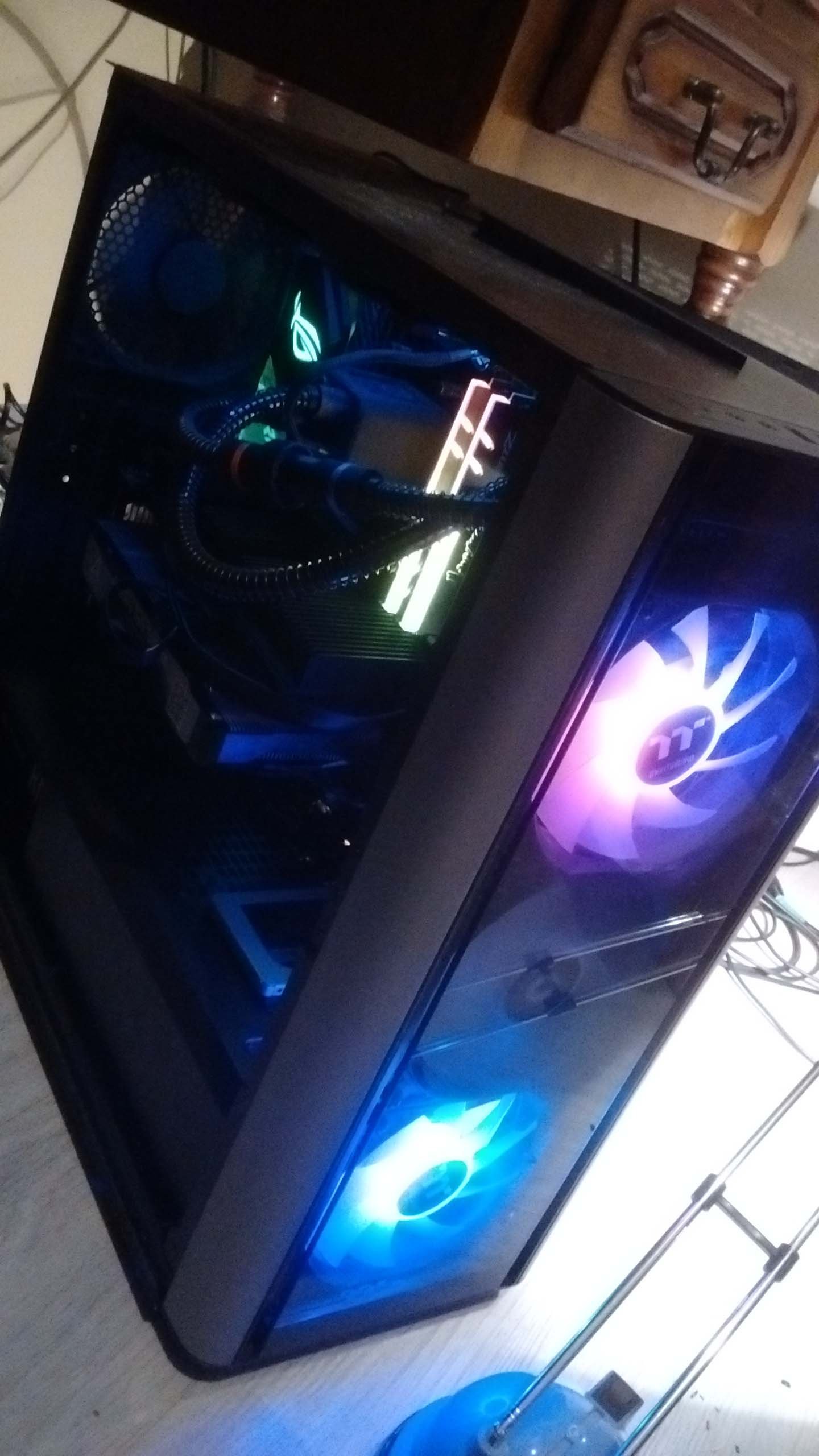
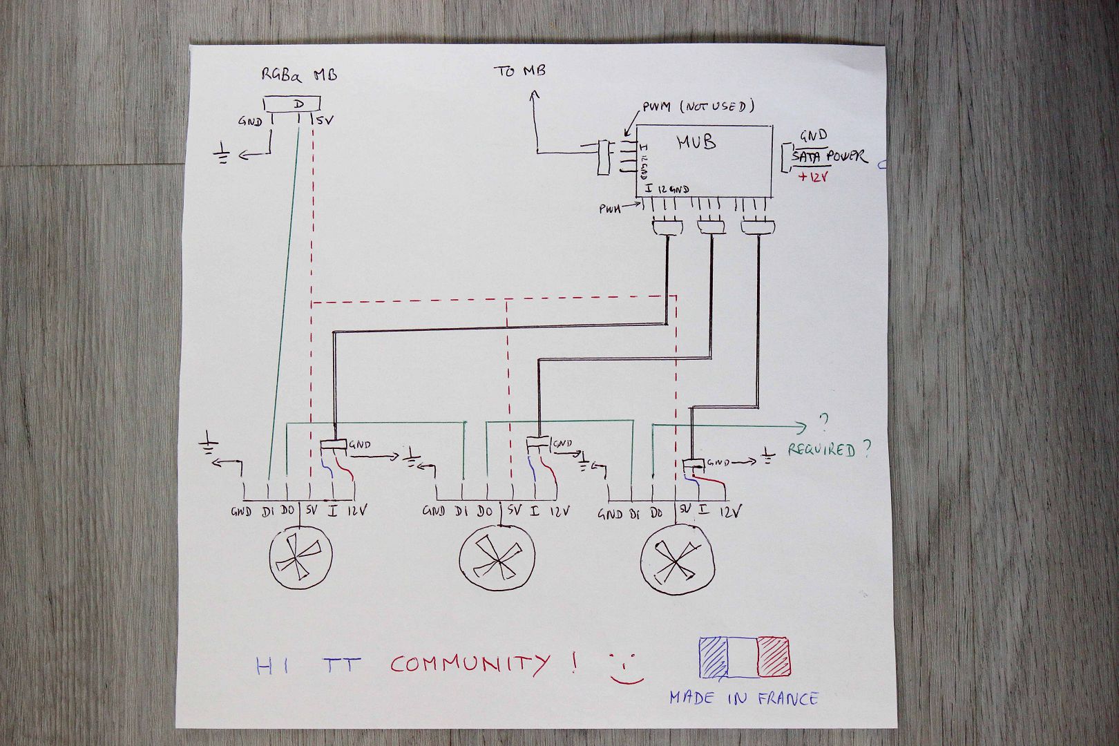
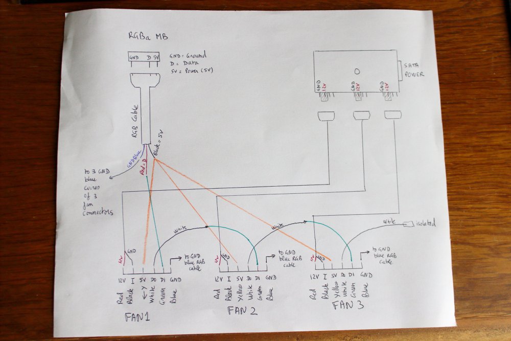
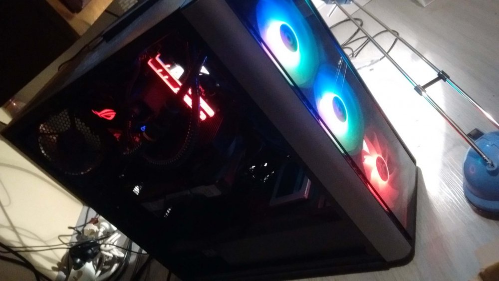
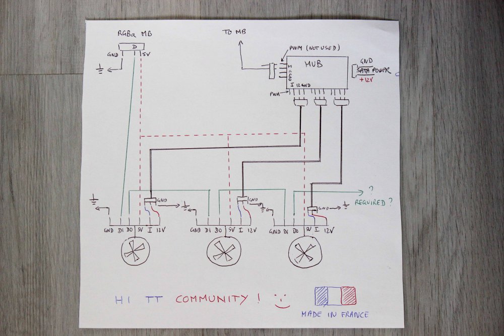
One more thing about that : we are not sure if this cable pinout is compatible with our fans. This cable have a four pin RGB, which is 12V RGV not adressable. And we don't know if the cable fans are mounted in series or parallel for RGB lightning. When I saw my fans working with the MB and rainbow effect, this was wonderful because the color of the three fans were different and move from one to the other like waves. I've never seen that since I have this case (october 2019...). It lasted 5 minutes... That motivate me to build a cable In LEVEL 20 MT : I think the three fans are mounted in series for RGB when MB is under control and parralel when the controller card is driving. On the other case, the three fans would be some clones with the same lightning pattern, like when control with the controller card. That would explain why there is a jumper between DI and DO (Data IN Data out) on connector 1 when there is two fans in the case, like Commander C36. On the Card we have these notes : 12V : Sure : power supply of fans for spinning I : I think it's de Information for rotation monitoring -> it would be possible to drive spinning speed from the MB with DC, because there is no PWM. On a fan, here is always 3 cables, 4 when PWM. Minimum is 3 cables : 12V, GND, and Tachometer. Think "I" is Tacho. 5V : Sure : it's power supply of RGB adressable DO : pretty sure : Data out DI : pretty sure : Data IN GND : Sure : ground I order that : https://fr.aliexpress.com/item/4000071997398.html?spm=a2g0s.9042311.0.0.289d6c37olewL2 So I will solder cables from the connector of Aliexpress and no modification on the case. Just plug the connector fan on it. Card to control speed with MB : https://''/item/4000463360337.html?spm=a2g0s.9042311.0.0.289d6c37olewL2 PWM cables that I will cut the head (and control cable not used, just 12V, GND and Tacho) : https://fr.aliexpress.com/item/32957428861.html?spm=a2g0s.9042311.0.0.289d6c37olewL2 30cm RGB 5V 3 pin (will cut the head) : https://fr.aliexpress.com/item/32989740896.html?spm=a2g0s.9042311.0.0.289d6c37olewL2 On first time I will test a fan with external 12V PS and the info cable of the hub to safely confirm that "I" is the tacho Info. After that I will test if I can synchronize one Fan with RGB driving by MB, and two, three... My wiring diagram : EDIT 28 FEBRUARY 2020 : Cplpunishr discovered I is not tacho but Ground. I comfirmed that, no information out of this pin when fan is spinning. I must be wired to ground. Also no need to plug the cable between PWM hub and the motherboard.
-
lol. We are all looking for same thing 😄. I've take a look to amazon a few time and i saw this adaptor, but it isn't available in amazon.fr. Link to Amazon.fr : https://www.amazon.fr/Unbranded-Adaptateur-ventilateur-broches-Molex/dp/B07D5DXL12 But the user review is.... He burned his RGB leds. I just buy a few minutes some stuff in aliexpress (RGB cable, PWM hub, Power SATA, 6 pin PH2 connectors ...). Maybe possible to wire three 6 pins PH2 connectors to 3 PWM cable, and a RGB 5V cable to the three 6 pin PH2. Then, plug the three PWM cables to a PWM hub. The idea is to bypass the controller without cut any cable on the case. Just make a cable to bypass. I will able to control speed fan with DC of motherboard and RGB directly. The hub, powered by SATA supply, will deliver enough power for 3 fans. The only thing that I understand, but I have a doubt : If I connect the data cable (central pin of 3 pin RGB outlet) from MB to the DI of the first FAN, and solder a cable from the DO pin of the first FAN to DI of second FAN and same for second to the third : It's like a ribbon of 27 led ? But the last DO ? Shoult it be kept empty ?
-
I think so, controller isn't compatible with Aura, but ONLY with X570 MB. I Don't think there is any people with a working card... It is weird issue. Just now I pushed to the RGB button and No led. Re pushed to return to chassis control. Then i saw he connector was unplugged. I plugged it with computer ON (hotplug), and re push RGB button : It worked ! I was in Armoury Crate with Rainbow effet and it was just wonderful effect, waw ! Without touch anything, I rebooted, the effect was still there. I shut down and restarted, effect gone... One led on first fan. When I built my rig since 4 month I saw it working two or three times. Each time I hotplugged RGB cable or SATA power cable.
-
Did you get this chassis or same controller card of other chassis to work with Asus X570 ? I tried many Asus Aura versions, with disabling lighting service (not physically removed) to get Aura working without all errors messages (stop working). No luck. I am now with Armoury Crate and no chance. This case won't work with Asus X570. It would be interesting if only one person who get it work can post here to see if it's possible !
-
Hi, People here with this issue : Morpheus 258 : Commander C36 + Tuf X570 DoomsSsday : View37 + Strix-E X570 maherrich : Commander C36 + Strix-F X570 GregAMD : View 37 + Prime TRX40 Roundgraph Level 20 MT + Strix-E X570 Juraz76 : Commander C34 + Strix-E X570 Saamushain ? + Tuf X570 plus wifi Jujunet : Level 20 MT + Strix-E X570 Atsf1317 : Level 20 MT + Strix-E X570 TT james answered that TT tested the controller card with Asus X570 Series and works perfectly. Looking for issue. No news anymore. Can someone in this forum who own one of these cases, with an Asus X570 or TRX40 post here. To know if they are numerous or not. It's not a coincidence or a defect. There is a real compatibility problem. The least we could do is send to these users a compatible card before they run out of warranty, or suggest a solution (quickly). These chassis are supposed to support Aura. Best Regards, Julien
-
Hello, What about this issue ? Any solution/workaround ?
-
In many tests we see that installing a WC heatsink in front position gives better temps on CPU vs heatsink on the top. Because rad air intake is lower in temperature. But this configuration isn't good for GPU because of the dissipated heat goes into the case. On the other hand, reverse is better for GPU temps because heat of CPU is going outside. I like these thermaltake cases because when you install the rad on the side you have the lower air intake temp AND expulsion of heat. so you have better temps inside the case. Have a GPU design with heat expulsion on the bracket is the best solution (or WC the CG). To answer your first question, I think it's the best solution for cooling. You can also install two fans on the top, it generate an air flow interesting for cooling VRM environment. For the hard drives, I have a LEVEL 20 MT, and you can install only one SSD behind the mobo, on the GT I don't know. For best temperature of drives, the best is on the low. Be careful of compatibility of a 360 on the top, is there enough place ? On this case I see there is a glass trempered on the right side, there is inevitably hot air going behind the mobo. On level 20 MT there is a steel lid with holes juste behind the place of the side rad too expulse hot air outside the case. There is inevitably hot air inflitration behind the mobo but it will be best than a lid completely closed.
-
@TT James : Thanks for investigations. My case is a Level 20 MT ARGB and I have the 3 front RGB fans connected to the controler card, so no jumper. The rear fan is connected directly to the motherboard. Board : Asus Strix-E X570. When I press for 3 seconds the RGB button, the 3 fans blinks and the fans are controlled by MB. But like the photo of RoundGraph or the video of Morpheus258 in the other thread, only one led of the top fan is illuminated. In my case, the color of this led change in coherence with the other leds in the MB when I use a Aura profile. On the other thread we can see Morpheus258 has a jumper on his card (two RGB fans).
-
I have the same issue. A we talked about that on this thread : We are three now on this forum with this issue... Seem like the controller card is not compatible with X570 Asus Boards. I have this even with UEFI loaded.
-
I have send them a message too, no response. It was a few days, don't remember, I have no email confirmation...
-
Yeah, 200 mm fans are also greate for the airflow, that's too bad, RGB 200mm fans are quite expensive.